GET THE Exclusive discounts today!


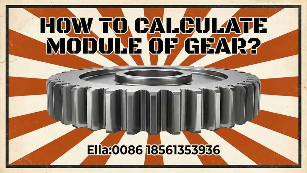
How to Calculate Module of Gear? The Complete Engineering Guide
Learn how to calculate the gear module using the outside diameter and number of teeth. Includes gear module formulas, examples, and conversion tips for metric gear design.
Jenny
4/9/20266 min read
How to Calculate Module of Gear? The Definitive Guide to Metric Gear Design
In the precision-driven world of mechanical engineering, the "Module" is the universal language of gears. If you are working with metric machinery, the module is the single most important parameter you will encounter. It determines the size of the teeth, the strength of the transmission, and, most crucially, whether two gears will actually mesh together.
If you are asking, "How to calculate module of gear?", you are likely in the middle of a design project or trying to replace a worn component in an existing system. Understanding the mathematics behind the module is not just an academic exercise; it is a fundamental skill for ensuring the longevity and efficiency of any drivetrain. In this comprehensive guide, we will break down the essential formulas, explore real-world measurement techniques, and provide step-by-step examples to help you master gear module calculation.
1. What is the Gear Module (m)?
Before we dive into the calculations, we must define what we are calculating. The Module (m) is a unit of measurement that indicates the size of a gear tooth. Technically, it is the ratio of the pitch diameter to the number of teeth.
In the metric system, as the module number increases, the size of the gear tooth also increases. A module 1 gear has very small, fine teeth, while a module 10 gear has massive teeth used in heavy industrial machinery. For two gears to mesh correctly, they must have the exact same module. This standardization is what allows engineers across the globe to design interchangeable components.
2. The Fundamental Gear Module Formula
The most basic way to calculate the module is based on the Pitch Diameter (D) and the Number of Teeth (z). The pitch diameter is the theoretical circle where the teeth of two meshing gears meet.
The fundamental formula is: m = D / z
In this equation:
m = Module (expressed in millimeters)
D = Pitch Diameter (expressed in millimeters)
z = Number of Teeth
For example, if you have a gear with a pitch diameter of 100 mm and it has 50 teeth, the calculation is straightforward: 100 divided by 50 equals a module of 2.
3. The Real-World Challenge: Calculating Module from Outside Diameter
While the formula m = D / z is technically perfect, it presents a practical problem: you cannot easily measure the pitch diameter of a physical gear with a caliper. The pitch diameter is an invisible, theoretical line.
In a workshop or repair setting, the only things you can accurately measure are the Outside Diameter (Da) (the very top of the teeth) and the Number of Teeth (z). Fortunately, there is a specific formula that connects these physical attributes to the module.
The formula for calculating the module from the outside diameter is: m = Da / (z + 2)
In this equation:
Da = Outside Diameter (Tip diameter)
z = Number of Teeth
Why "+ 2"? In standard gear design, the "Addendum" (the height of the tooth above the pitch circle) is equal to 1 module. Since there are two sides to the diameter, you add 2 modules to the pitch diameter to get the outside diameter.
Step-by-Step Example:
Imagine you have a gear in your hand. You count the teeth and find there are 28. You take your digital caliper and measure the outside diameter at 60mm.
Add 2 to the tooth count: 28 + 2 = 30.
Divide the outside diameter by this number: 60 / 30 = 2.
The module of your gear is 2.
4. Reverse Engineering: Finding Pitch Diameter and Outside Diameter
Once you know the module of a gear, you can calculate all other dimensions. This is essential when you are designing a new gear from scratch.
To find the Pitch Diameter (D): D = m * z If you decided to design a gear with a module of 4 and you need 40 teeth, your pitch diameter will be 160 mm.
To find the Outside Diameter (Da): Da = m * (z + 2). Using the same example (m=4, z=40), the outside diameter would be 4 multiplied by 42, which equals 168 mm. Knowing this measurement allows you to ensure the gear will fit inside its housing without interference.
5. Calculating Module for Helical Gears
Calculating the module for helical gears is slightly more complex because the teeth are cut at an angle. In helical gearing, we distinguish between the Normal Module (mn) and the Transverse Module (mt).
The Normal Module is the measurement perpendicular to the teeth, which is what the cutting tool (the hob) uses. The Transverse Module is the measurement in the plane of rotation. To find the module of a helical gear, you must account for the Helix Angle (β).
The formula is: mn = mt * cos(β)
When you are measuring a physical helical gear, you usually calculate the transverse module first using the outside diameter formula, and then use the helix angle to find the normal module. This ensures that you select the correct cutting tool for manufacturing.
6. Module vs. Diametral Pitch: Converting Between Systems
If you are working with machinery from the United States, you may encounter Diametral Pitch (P) instead of the module. While the module is the ratio of diameter to teeth (m=D/zm=D/z), the diametral pitch is the inverse: the ratio of teeth to diameter (P=z/DP=z/D).
To convert between these two systems, use these constants:
m = 25.4 / P
P = 25.4 / m
For example, if you have a gear with a Diametral Pitch of 8, the metric module equivalent would be 25.4 divided by 8, which is 3.175. Since this is not a standard metric module, it tells you that the gear was designed using the Imperial system, and a standard metric gear will not mesh with it.
7. Understanding Standard Module Values
In the world of manufacturing, we don't just use any random number for the module. To ensure cost-effectiveness and tool availability, international standards (ISO) have defined a series of "Preferred" module values.
Common standard modules include:
Small Gears: 0.5, 0.8, 1.0, 1.25, 1.5, 1.75
Medium Gears: 2.0, 2.25, 2.5, 2.75, 3.0, 4.0
Large Gears: 5.0, 6.0, 8.0, 10.0, 12.0
When you calculate a module and get a result like 1.98 or 2.02, it is almost certain that the intended module was 2.0. Small deviations in your measurement are usually due to tooth wear or manufacturing tolerances. Always look for the nearest standard value.
8. Why Center Distance Depends on the Module
If you are designing a gear train, the module determines the Center Distance (a) between the two shafts. If your module calculation is wrong, the shafts will be either too close (causing the gears to jam) or too far apart (causing excessive backlash and tooth failure).
The formula for the center distance of two meshing gears is: a = [m * (z1 + z2)] / 2
This formula shows that the module is the scaling factor for the entire mechanical system. Even a small error in the module will be magnified across the center distance, leading to a system that simply does not work.
9. Common Mistakes to Avoid in Module Calculation
Through our years of custom gear manufacturing, we have seen several recurring errors when clients calculate their own modules:
Measuring the Wrong Diameter: Ensure you are measuring the true outside diameter across the center of the gear. If the gear has an odd number of teeth, you cannot measure directly across the top of two teeth; you must use a specialized technique or a gear pitch gauge.
Ignoring Tooth Wear: On a very old gear, the tops of the teeth (the outside diameter) may be worn down. This will result in a calculated module that is smaller than the original. In these cases, it is better to measure the "Root Diameter" or use a specialized micrometer to measure across a specific number of teeth.
Unit Confusion: Always ensure your measurements are in millimeters. If you measure in inches and apply the metric formula, the result will be nonsensical.
10. Conclusion: Precision Starts with the Module
So, how to calculate module of gear? Whether you use the pitch diameter (m = D / z) or the more practical outside diameter method (m = Da / (z + 2)), the goal is the same: to find the "size signature" of the gear.
Accuracy in this calculation is the difference between a machine that runs silently for years and one that fails within hours. As gears become more specialized and tolerances become tighter, the ability to correctly identify and calculate the module remains the most essential skill in any engineer's toolkit.
Qingdao Novi Machinery is a professional gear manufacturer. We specialize in the high-precision gear manufacturing and Custom Gear Production across all standard and custom modules. Our state-of-the-art CNC facilities can handle everything from micro-gears to massive industrial drives. If you are struggling to identify the module of a complex or worn gear, our engineering team is here to help with professional measurement and reverse-engineering services.
Are you ready to start your next gear project? Contact us today for a technical consultation and a custom quote!
Looking for a reliable gear supplier for your project?
Send us your drawings or technical requirements, and our engineering team will provide a professional gear solution.
Address:huangdao district,Qingdao city,Shandong province,China
© 2026. All rights reserved.
Quick Link