GET THE Exclusive discounts today!


What is a Gear Train?The Complete Guide to Mechanical Transmission
What is a gear train and how does it work? Explore our definitive guide on simple, compound, and planetary gear trains. Learn about gear ratios, mechanical advantage, and industrial applications.
Sam
3/5/20266 min read
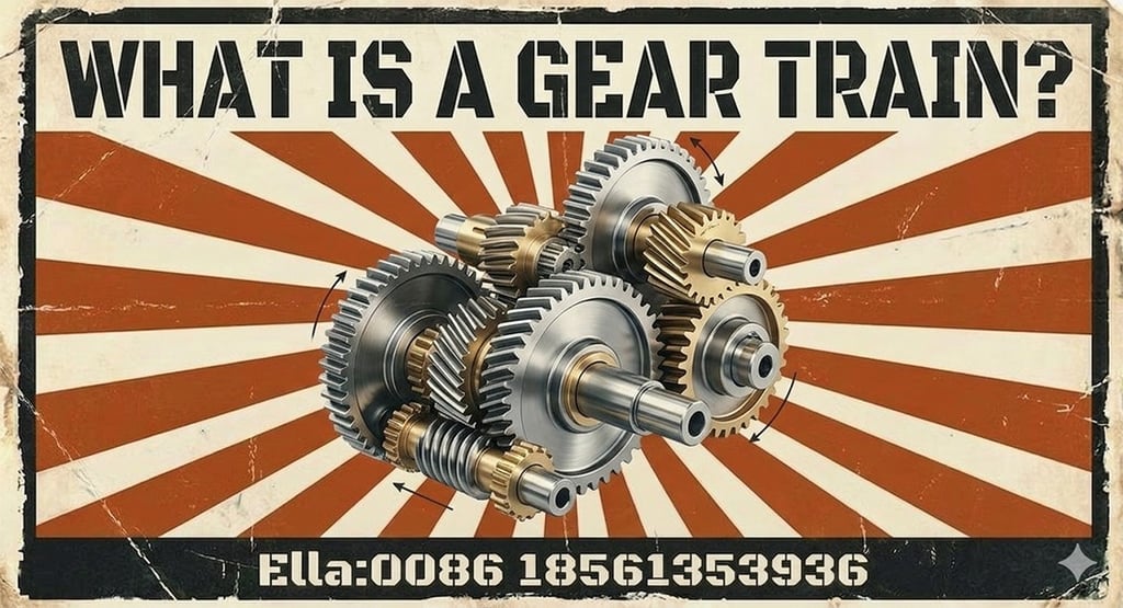
What is a Gear Train? The Definitive Guide to Mechanical Transmission Systems
In the world of mechanical engineering, a single gear is an impressive piece of geometry, but it is effectively useless on its own. To perform work—to lift a car, to turn a windmill, or to move a robotic arm—gears must work in harmony. When two or more gears are meshed together to transmit power from one shaft to another, they form what is known as a gear train.
If you are asking, "What is a gear train?", you are looking at the foundation of the machine age. A gear train is a mechanical system formed by mounting gears on a frame so that the teeth of the gears engage. This allows for the transfer of motion and the manipulation of torque and speed. In this comprehensive guide, we will explore the different configurations of gear trains, the mathematics of gear ratios, and the industrial applications that make these systems indispensable.
1. The Core Purpose: Why Do We Use Gear Trains?
The fundamental reason we use a gear train is to achieve a mechanical advantage. Most power sources, such as electric motors or internal combustion engines, produce power at a specific speed and torque that is rarely a perfect match for the task at hand.
A gear train acts as a mechanical "transformer." It can take a high-speed, low-torque input and transform it into a low-speed, high-torque output (speed reduction). Conversely, it can take a slow rotation and speed it up. Furthermore, gear trains are used to change the direction of rotation or to transmit power across a distance between two shafts. Without the gear train, our motors would be too weak to move heavy loads, and our machines would be too fast to control.
2. Basic Components: Driver, Driven, and the Idler Gear
To understand how a gear train functions, one must identify the roles of the individual gears within the set.
The Driver Gear is the gear attached to the power source (the input shaft). It provides the initial motion. The Driven Gear (or Follower) is the gear attached to the output shaft, which performs the final work.
However, many gear trains include an Idler Gear. This is a gear placed between the driver and the driven gear. Interestingly, an idler gear does not affect the overall gear ratio of the system, no matter how many teeth it has. Its primary purposes are to change the direction of the output rotation (making the driver and driven gear rotate in the same direction) or to bridge a physical gap between two shafts without requiring massive, heavy gears.
3. Simple Gear Trains: Linear Power Transfer
The most basic configuration is the Simple Gear Train. In this setup, each shaft carries only one gear. The gears are arranged in a single line.
In a simple gear train, the gear ratio is determined solely by the number of teeth on the first gear and the last gear. Any gears in the middle are idlers.
Direction of Motion: In a two-gear simple train, the driver and driven gears rotate in opposite directions. If you add a third gear (an idler), the input and output gears will rotate in the same direction.
Applications: Simple gear trains are used where space is not a major constraint and where the required speed reduction is relatively small. You will find them in basic clockwork, simple toys, and some manual hand tools.
4. Compound Gear Trains: Maximizing Space and Torque
When a large speed reduction is required in a small space, a simple gear train becomes impractical because the driven gear would have to be enormous. The solution is the Compound Gear Train.
In a compound gear train, at least one shaft carries two gears of different sizes that rotate together at the same speed. Power is transmitted from the first shaft to the first gear on the second shaft. Then, the second gear on that same shaft transmits power to a third shaft.
The Power of Multiplication: The total gear ratio of a compound train is the product of the ratios of each individual meshing pair. This allows for massive speed reductions (or increases) in a very compact footprint.
Applications: Compound gear trains are the "engines" inside industrial gearboxes, automotive transmissions, and heavy-duty winches. They allow a small motor to generate the massive torque required to move tons of material.
5. Reverted Gear Trains: The Coaxial Solution
A Reverted Gear Train is a specialized version of a compound gear train where the input shaft and the output shaft are coaxial—meaning they lie on the same straight line.
To achieve this, the gears are arranged so that the distance between the centers of the first pair of gears is exactly equal to the distance between the centers of the second pair.
Advantages: This configuration is incredibly space-efficient. Because the input and output are aligned, the system is much easier to house in a cylindrical casing.
Applications: This is the classic design for clock mechanisms (where the hour and minute hands must rotate on the same axis) and for compact industrial speed reducers.
6. Epicyclic (Planetary) Gear Trains: The Pinnacle of Design
The most complex and high-performing system is the Epicyclic Gear Train, more commonly known as a Planetary Gear Train. Unlike the previous types where gear axes are fixed in space, in a planetary system, some gears can move around other gears.
A planetary gear set consists of four main components:
The Sun Gear: The central gear.
The Planet Gears: Several smaller gears that mesh with the sun gear.
The Planet Carrier: A frame that holds the planet gears and allows them to rotate around the sun gear.
The Ring Gear (Annulus): An outer ring with internal teeth that meshes with the planet gears.
By holding one of these components stationary and using the others as input and output, engineers can achieve multiple gear ratios and directions from a single gear set.
Why use them? They offer the highest torque-to-weight ratio of any gear train. The load is shared across multiple planet gears, which reduces wear and increases the lifespan of the system.
Applications: Modern automatic transmissions, electric vehicle drivetrains, robotics, and aerospace actuators rely almost exclusively on planetary gear trains.
7. Mathematics of the Train: Calculating the Gear Ratio
Understanding the "Speed Ratio" is vital for any industrial application. The gear ratio is generally defined as the number of teeth on the driven gear divided by the number of teeth on the driver gear.
In a Simple Train, if the driver has 10 teeth and the driven has 50, the ratio is 5:1. The output moves five times slower but with five times the torque.
In a Compound Train, the math becomes more interesting. If the first pair is 5:1 and the second pair is 4:1, the total ratio is 20:1 (5 multiplied by 4). This multiplicative property is why compound trains are so effective at generating torque.
8. Design Considerations for High-Performance Gear Trains
Building a gear train is about more than just meshing teeth. As a manufacturer, we must consider several critical technical factors:
Backlash: This is the slight gap between mating teeth. While necessary to prevent jamming and allow for lubrication, too much backlash in a gear train causes "play" and inaccuracies, which is unacceptable in robotics or CNC machinery.
Efficiency: Every time a gear meshes with another, a small amount of energy is lost to friction. In a long simple gear train, these losses can add up. Compound and planetary systems are often designed to minimize these losses.
Lubrication and Cooling: Because gear trains involve multiple contact points, heat management is essential. High-quality gear trains often operate in an "oil bath" or use forced lubrication systems to ensure the teeth stay cool and friction is minimized.
Center Distance: The frame holding the gear train must be machined with extreme precision. If the shafts are even a fraction of a millimeter too close or too far apart, the gears will either jam or wear out prematurely.
9. Conclusion: The Power of the System
So, what is a gear train? It is the ultimate expression of mechanical coordination. It is a system that takes the raw, untamed power of a motor and refines it into the precise speed and torque required to move the world. Whether it is a simple two-gear set in a household appliance or a complex planetary array in a deep-space probe, the gear train remains the most reliable way to transmit power.
At Qingdao Novi Machinery, we specialize in the design and manufacture of high-precision gear trains. We don't just provide gears; we provide transmission solutions. Our engineering team works with you to calculate the ideal ratios, select the best gear types (spur, helical, or bevel), and build a gear train that is quiet, efficient, and durable.
Need a custom gear train for your next project? Contact our engineering specialists for a consultation today!
Looking for a reliable gear supplier for your project?
Send us your drawings or technical requirements, and our engineering team will provide a professional gear solution.
Address:huangdao district,Qingdao city,Shandong province,China
© 2026. All rights reserved.
Quick Link