GET THE Exclusive discounts today!


What Is Module In Gear?
Master the gear module concept. Learn the module formula, how to calculate it from tip diameter, and the difference between Metric Module and Diametral Pitch.
jenny
3/3/20266 min read
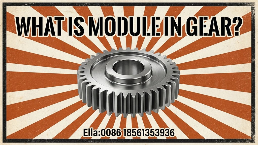
What is Module in Gear? The Definitive Guide to Gear Standardization and Design
In the intricate world of mechanical engineering, where precision is the difference between a high-performance machine and a catastrophic failure, one term stands above the rest in importance: The Module.
If you have ever looked at a set of gears and wondered why some mesh perfectly while others fail to align, the answer almost always lies in the module. But what is it exactly? Is it a measurement of size? A ratio? Or a global standard?
In this comprehensive guide, we will break down the concept of the gear module, explain the mathematics behind it, compare it to its Western counterpart (Diametral Pitch), and show you how to apply it in real-world engineering.
1. The Core Definition: What is a Gear Module?
In the metric system, the Module (m) is the fundamental unit used to indicate the size of gear teeth. Specifically, it is defined as the ratio of the Pitch Circle Diameter (D) to the Number of Teeth (Z).
The Featured Snippet Definition:
Module (m) = Pitch Circle Diameter (mm) / Number of Teeth.
It represents the number of millimeters of pitch diameter per tooth. The larger the module, the larger and stronger the gear teeth.
Unlike measuring the physical width of a tooth with a caliper, the module provides a standardized reference that ensures gears are compatible. If two gears are to mesh together smoothly, they must have the exact same module.
2. The Geometry of the Pitch Circle
To understand the module, you must first understand the Pitch Circle. When two gears mesh, they behave as if they are two smooth cylinders rolling against one another without slipping. These imaginary cylinders are the pitch circles.
The diameter of this circle is the Pitch Diameter (D). This is not the outer diameter of the gear (the tip of the teeth), but a theoretical line roughly in the middle of the tooth height.
Because we cannot easily count the "mm" of a curved circle, the module simplifies the relationship:
D=m×ZD=m×Z (Pitch Diameter = Module × Number of Teeth)
Z=D/mZ=D/m (Number of Teeth = Pitch Diameter / Module)
3. Why the Module System is Mandatory for Modern Engineering
Before the standardization of the module, gear manufacturing was a chaotic landscape of custom sizes. The module system, standardized by ISO (International Organization for Standardization) and DIN (Deutsches Institut für Normung), solved three critical problems:
A. Global Interchangeability
A gear manufactured in Germany with a Module 2.0 will mesh perfectly with a gear manufactured in Japan or China with a Module 2.0. This allows for a global supply chain where parts can be sourced from different vendors with 100% compatibility.
B. Simplified Calculations
Instead of dealing with complex fractions of an inch or decimal points in circular pitch, engineers can use whole numbers or standard increments (e.g., Module 1, 1.5, 2, 2.5). This makes designing gearboxes significantly faster and reduces human error during the drafting phase.
C. Predictive Strength Analysis
Since the module directly dictates the size of the tooth, it is the primary variable in the Lewis Formula used to calculate bending stress. A higher module means a thicker "root" at the base of the tooth, allowing the gear to transmit higher torque without shearing.
4. Module vs. Diametral Pitch (DP): The Metric vs. Imperial Rivalry
If you are working in the United States or the UK (on legacy systems), you might encounter Diametral Pitch (DP) instead of the module.
Module (Metric): Measures how many millimeters of diameter there are per tooth. (Formula: D/ZD/Z)
Diametral Pitch (Imperial): Measures how many teeth there are per inch of diameter. (Formula: Z/DZ/D)
The Inverse Relationship
The module and DP are mathematical inverses.
As the Module increases, the teeth get larger.
As the Diametral Pitch increases, the teeth get smaller.
How to Convert Between Module and DP
To convert between the two systems, use the constant 25.4 (the number of millimeters in an inch):
Module = 25.4 / Diametral Pitch
Diametral Pitch = 25.4 / Module
Example: A gear with a Diametral Pitch of 10 is equivalent to a Module of 2.54.
5. Standard Module Sizes: The ISO and DIN Norms
You cannot simply choose any number for a module. To keep manufacturing costs low, industry standards dictate "Preferred" and "Second Choice" modules. Using standard sizes ensures that you can buy off-the-shelf hobbing tools and cutters.
Common "Preferred" Modules (in mm):
Micro Gears: 0.1, 0.2, 0.3, 0.5
Small Machinery: 1.0, 1.25, 1.5, 2.0, 2.5
Heavy Industrial: 3, 4, 5, 6, 8, 10
Massive Infrastructure: 12, 16, 20, 25+
Pro Tip for Designers: Always try to use "Series 1" (Preferred) modules in your designs. Choosing a 2.1 module instead of a 2.0 will force you into expensive, custom tool manufacturing.
6. How the Module Dictates Gear Anatomy
The module is not just a ratio; it is the "DNA" of the gear tooth. Once the module is set, almost every other dimension of the tooth is derived from it:
Addendum (ha): The height from the pitch circle to the top of the tooth. Usually ha=1×mha=1×m.
Dedendum (hf): The depth from the pitch circle to the bottom of the tooth. Usually hf=1.25×mhf=1.25×m.
Whole Depth: The total height of the tooth (ha+hf=2.25×mha+hf=2.25×m).
Circular Pitch (P): The distance from one point on a tooth to the same point on the next tooth along the pitch circle. P=π×mP=π×m.
This means that if you know the module of a gear, you can reconstruct almost its entire geometry just by looking at it.
7. Practical Step-by-Step: How to Calculate the Module of an Unknown Gear
Imagine you are in a maintenance shop and need to replace a broken gear, but you have no documentation. How do you find the module?
Step 1: Count the Teeth (Z)
Simple enough. Let’s say you count 30 teeth.
Step 2: Measure the Tip Diameter (da)
Use a digital caliper to measure the outermost diameter of the gear (from tooth tip to tooth tip). Let's say it measures 64 mm.
Step 3: Apply the Formula
For a standard spur gear, the formula for Tip Diameter is:
da=m×(Z+2)da=m×(Z+2)
Rearrange the formula to solve for the Module:
m=da/(Z+2)m=da/(Z+2)
Step 4: Calculate
m=64/(30+2)m=64/(30+2) m=64/32m=64/32 m=2.0m=2.0
The module of your mystery gear is 2.0.
8. Module in Advanced Gearing: Helical and Bevel Gears
While the module is straightforward in Spur Gears, it becomes more complex in other gear types:
Helical Gears
Helical gears have two modules: the Normal Module (mn) and the Transverse Module (mt).
The Normal Module is measured perpendicular to the tooth flutes and is used for selecting the cutting tool.
The Transverse Module is measured in the plane of rotation. They are related by the helix angle (ββ): mn=mt×cos(β)mn=mt×cos(β).
Bevel Gears
In bevel gears, the module changes along the length of the tooth because the gear is conical. By convention, the "Module" of a bevel gear always refers to the Large End of the tooth.
9. FAQ: Frequently Asked Questions about Gear Modules
Can I mesh a Module 2.0 gear with a Module 2.5 gear?
No. Even if they are made of the same material and have the same width, they will not mesh. The tooth profiles are different sizes, and the center distance will not align. Attempting to force them will lead to immediate tooth failure.
What is the "Pressure Angle" and does it relate to the module?
The Pressure Angle (usually 20° or 14.5°) is the angle at which power is transmitted between gears. While it is independent of the module, both the module and the pressure angle must match for gears to mesh.
Why do some small gears have very high modules?
This is rare. Usually, a high module on a small diameter results in a "Pinion" with very few teeth (e.g., 6 or 8 teeth). This can cause undercutting, which weakens the gear. In such cases, designers often use "Profile Shifting."
10. Conclusion: The Module as the Language of Motion
The module is more than just a math formula; it is the universal language that allows machines to speak to one another. From the tiny gears inside your digital camera’s zoom lens to the massive gears in a wind turbine, the module ensures that motion is transmitted efficiently, predictably, and safely.
For engineers and designers, mastering the module is the first step toward creating robust mechanical systems. By sticking to standard modules, understanding the trade-offs between speed and torque, and knowing how to convert between Metric and Imperial systems, you ensure your designs are ready for the global stage.
Looking for a reliable gear supplier for your project?
Send us your drawings or technical requirements, and our engineering team will provide a professional gear solution.
Address:huangdao district,Qingdao city,Shandong province,China
© 2026. All rights reserved.
Quick Link