
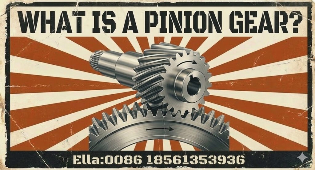
A pinion gear is a key component in mechanical power transmission, connecting motors, gearboxes, and driven machinery through controlled tooth engagement. Pinions are used in applications ranging from compact transmission stages to heavy-duty industrial drives in mining mills, cement kilns, rolling mills, paper machines, sugar mills, wind turbines, and port cranes.
Selecting the right pinion requires more than matching its diameter or tooth count. Engineers must consider gear geometry, torque, speed, loading conditions, material properties, heat treatment, lubrication, alignment, and compatibility with the mating gear. These factors determine transmission performance, reliability, and service life.
This guide explains how pinion gears work, the main types used in industry, the engineering parameters that govern their design, common failure mechanisms, and practical considerations for selecting or replacing an industrial pinion.
1. What Is a Pinion Gear?
A pinion gear is a gear that meshes with another gear or a toothed rack to transmit motion and force. In many gear pairs, the pinion is the smaller member, while the larger mating component is called the gear, wheel, or—in certain heavy-duty open drives—the bull gear or girth gear.
The word pinion describes a gear’s role within a mechanism rather than one specific tooth geometry. A pinion may have spur, helical, or bevel teeth, depending on the shaft arrangement and transmission design.
Pinions can serve as either driving or driven components:
- Driving pinion: Receives torque from a motor, gearbox, or shaft and transfers it to the mating gear.
- Driven pinion: Receives motion from another gear and transmits it to a downstream component.
For an external gear pair, the gear with fewer teeth generally rotates faster than the gear with more teeth. The tooth-count relationship establishes the nominal speed ratio, while the transmitted torque depends on the ratio, losses, and operating conditions.
Several parameters define a pinion:
- Number of teeth (z): The total number of teeth on the gear.
- Module (m): A metric measure of tooth size, commonly defined for a spur gear by m=d/z, where d is the reference diameter.
- Reference diameter (d): The diameter of the reference pitch circle used for gear geometry calculations.
- Pressure angle: A parameter defining the direction of tooth contact force in the transverse plane for standard involute gearing.
- Helix angle: The angle of the tooth trace relative to the gear axis for helical gearing.
In large industrial machinery, a mill pinion may mesh with a large girth gear to drive a rotating drum. In a crane slewing system, a slewing pinion engages with a slewing ring gear to rotate the upper structure. Although both are pinions, their loads, geometry, mounting arrangements, and maintenance requirements can differ substantially.
2. How Does a Pinion Gear Work?
A pinion transmits motion through successive engagement between its teeth and those of the mating gear. As one tooth pair moves out of contact, another pair engages, maintaining transmission of rotary motion when the gears are properly designed, manufactured, lubricated, and aligned.
Gear ratio and speed relationship
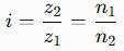
For a simple external gear pair, the magnitude of the gear ratio can be expressed as:
Where:
- z1 and z2 are the tooth counts of the driving and driven gears, respectively.
- n1 and n2 are their rotational speeds.
For example, when a pinion drives a gear with more teeth, the driven gear rotates more slowly. Ideally, its available torque increases in proportion to the ratio; actual output torque is lower because of transmission losses. Two externally meshing gears rotate in opposite directions.
The relationship between transmitted torque, power, and rotational speed is also important when selecting a pinion. A design must withstand both the tooth contact forces and the bending stresses at the tooth roots. Dynamic loads, starts and stops, reversals, and shock loading can increase the demands beyond those implied by steady-state power alone.
Pinion-and-gear versus rack-and-pinion
A conventional pinion-and-gear pair transfers rotary motion between rotating shafts. A rack-and-pinion system instead uses a rotating pinion to move a straight toothed rack, converting rotary motion into linear motion or vice versa.
These arrangements have different design requirements. A rotating industrial drive may prioritize torque capacity, gear contact, and shaft alignment, while a rack-and-pinion system also requires control of linear positioning, mounting geometry, and travel accuracy.
3. Common Types of Pinion Gears
Pinions are classified primarily by tooth geometry and the relationship between the connected shafts.
Spur and helical pinions
Spur pinions have straight teeth parallel to the shaft axis. They are relatively straightforward to manufacture and inspect, and they are used in many enclosed gearboxes and industrial transmission stages.
Helical pinions have teeth inclined to the shaft axis. Their engagement is more gradual than that of spur gears, which can support smoother operation under suitable conditions. However, helical gearing generates axial thrust that must be accommodated by the shaft, bearings, and housing. When specifying a helical drive, engineers should ensure that the helical gear shafts and thrust bearings are sized to handle the axial load produced by the pinion.
Double-helical or herringbone pinions combine opposing helix directions to reduce or balance axial thrust when the geometry and arrangement are appropriately designed.
Bevel pinions and rack-and-pinion drives
Bevel pinions transmit motion between intersecting shafts, commonly where the transmission must change direction. Their design must match the mating bevel gear’s geometry and mounting arrangement.
In rack-and-pinion drives, the pinion engages a linear rack. This configuration is widely used in positioning and movement systems, including selected crane and industrial handling mechanisms.
The pinion must be designed for the actual operating load, contact pattern, and required motion accuracy rather than selected solely by nominal dimensions.
Mill pinions and large industrial drive pinions
A mill pinion is commonly used in heavy-duty open gearing, where it meshes with a large girth gear mounted around a rotating drum. Such arrangements are found in ball mills, SAG mills, rod mills, and selected cement and mineral-processing equipment.
These drives can experience high torque, cyclic loading, contamination, and challenging lubrication conditions. Pinion geometry, shaft support, installation alignment, tooth contact, and the condition of the mating girth gear are therefore critical to reliable operation.
Not every large industrial gear is a pinion, and not every pinion drives a girth gear. The correct description depends on the actual transmission arrangement.
4. Key Pinion Gear Design Parameters
A reliable pinion design must satisfy geometric compatibility, tooth strength, surface durability, and the constraints of the complete drive system. Increasing tooth size or face width alone does not guarantee adequate performance; the shaft, bearings, housing, lubrication, and mating gear must also support the applied load.
Gear Geometry and Compatibility
The most important geometric parameters include:
- Module and tooth count: For a standard spur gear, the reference diameter is d=mz. For helical gears, engineers must distinguish normal module from transverse module and use the appropriate geometry conventions.
- Pressure angle: Affects tooth geometry, contact forces, and the balance between load capacity and radial bearing load.
- Helix angle and hand: For helical pinions, these must be compatible with the mating gear and shaft arrangement.
- Face width: Influences load distribution across the tooth face. More width is not automatically beneficial if alignment or shaft deflection causes uneven contact.
- Backlash and center distance: Affect meshing, thermal operating conditions, lubrication space, and the risk of interference or excessive clearance.
When replacing an existing pinion, nominal dimensions are only the starting point. Tooth profile, modifications, mounting geometry, and the mating gear’s condition can all affect compatibility.
Load Capacity, Materials, and Heat Treatment
Pinion strength must be evaluated against both tooth-root bending stress and tooth-flank contact stress. Engineers should consider transmitted torque, rotational speed, starts and stops, reversing duty, shock loads, and the expected operating life.
Steel is widely used for heavy-duty pinions, but the appropriate grade and treatment depend on the design. Options may include through-hardening, induction hardening, nitriding, or case hardening. Case-hardened pinions can combine a wear-resistant surface with a tougher supporting core when the material and treatment are properly specified. For a custom 40Cr spur gear,the chromium-alloy grade is typically paired with a defined hardening cycle so that tooth-root strength and flank durability match the applied torque.
For large mill pinions, rolling mill drives, and other high-load applications, the design should also account for shaft deflection, bearing stiffness, tooth contact distribution, lubrication, and environmental contamination.
Accuracy and Standards
The required gear accuracy should reflect the application’s speed, noise, load distribution, and service requirements. ISO 1328-1 addresses flank tolerance classification for cylindrical gears, while the ISO 6336 series provides methods for evaluating the load capacity of spur and helical gears. Applicable AGMA standards may also be used when specified by the project or customer. These standards cover different aspects of gear design and inspection, so the required standard and acceptance criteria should be agreed upon explicitly.
5. Pinion Gear Applications Across Major Industries
Pinions are used throughout heavy industry, but their functions vary with the equipment’s transmission architecture.
Mining and Cement Plants
In mining, mill pinion gears commonly drive the girth gears of ball mills, SAG mills, and rod mills. These large open-gear drives transmit substantial torque and must operate reliably under demanding production conditions.
Cement plants use pinions in rotary kiln and cement mill drives, including arrangements where a pinion meshes with a large external girth gear. Maintenance teams should inspect the pinion and mating gear together, checking tooth contact, lubrication, alignment, and wear.
Sugar Mills and Cane Processing
Sugar mills use pinions in cane mill and cane crusher drives, shredder systems, and other heavy-duty transmission arrangements. Depending on the equipment, the pinion may engage with a large bull gear, crown gear, or another gear within an enclosed gearbox.
For sugar mill pinion replacement, engineers should verify the original tooth geometry and mating component rather than relying on a generic description such as crown pinion. Terminology can vary between equipment designs and manufacturers.
Rubber Machinery
Pinions and gear pairs are used in rubber mills, open mixing mills, internal mixers, Banbury mixers, calenders, and extruder drive systems. Some applications require high torque at relatively low output speeds, while others operate under variable loads or reversing conditions.
For rubber machinery drive gears, practical selection priorities include tooth-root strength, contact durability, alignment, lubrication, and compatibility with the existing gearbox or open-gear arrangement. The pinion’s duty cycle and operating environment should guide material and heat-treatment choices.
Steel Plants and Rolling Mills
Steel production equipment uses pinions in rolling mill drives, pinion stands, coilers, recoilers, converter tilting systems, and selected sinter plant machinery. These applications can involve heavy loads, repeated starts and stops, and—in some drives—frequent reversals.
A pinion’s suitability depends on the specific machine and transmission design. For replacement work, engineers should establish the required geometry, material condition, shaft interface, and load requirements before deciding whether the pinion alone can be replaced.
Paper Mills
Paper machine drive systems may contain pinions in transmission stages serving refiners, pulpers, calenders, rewinders, and selected dryer-cylinder drives. The actual gear arrangement varies with machine layout and drive architecture.
When planning paper machine gear replacement, verify the tooth geometry, mounting arrangement, and operating requirements. A replacement pinion must mesh correctly with its mating gear and preserve the intended transmission ratio and alignment.
Marine and Heavy-Duty Equipment
Pinions appear in marine reduction gearboxes, heavy-duty winches, dredger cutter-head drives, and other marine transmission systems. Their geometry and loading depend on whether they are part of an enclosed reduction gearbox, an open drive, or a specialized mechanism.
For large marine replacement gears, engineers should assess torque and duty cycle alongside corrosion exposure, lubrication, bearing support, and the constraints of the existing assembly.
Power Generation and Wind Turbines
Wind turbines contain pinions in gearbox stages and in yaw and pitch systems. Within a gearbox, pinions may be part of parallel-shaft or other gear stages; in yaw and pitch systems, pinions may engage large ring gears to orient the nacelle or adjust blade pitch.
These functions should not be confused. A wind turbine yaw pinion and a gearbox pinion can differ in geometry, operating speed, loading, and inspection requirements. Replacement selection must match the specific system.
Port Cranes and Slewing Systems
Port cranes, container cranes, tower cranes, and mobile cranes may use slewing pinions to engage a slewing ring gear and rotate the crane’s upper structure. Pinions are also used within hoisting, luffing, trolley, and gearbox drives.
For a slewing pinion, engineers should consider the mating ring gear, mounting and bearing arrangement, load distribution, backlash, and operating environment. A correct replacement requires compatibility with the complete drive—not simply a matching tooth count.
6. Common Pinion Gear Failure Modes and Prevention
Pinion damage may result from tooth fatigue, surface distress, poor lubrication, contamination, alignment errors, or excessive loading. The visible damage is not always the original cause, so inspection should include the mating gear and supporting components.
| Failure mode | Possible contributing factors | Inspection or prevention |
|---|---|---|
| Pitting or surface fatigue | Contact stress, lubrication condition, or unsuitable material properties | Inspect tooth flanks, lubricant condition, and load distribution |
| Scuffing or scoring | Lubrication breakdown, high friction, or excessive local temperature | Check lubricant supply, tooth surfaces, and operating conditions |
| Tooth-root cracking | Repeated bending loads, overload, or stress concentration | Inspect tooth roots and investigate the load history |
| Uneven tooth wear | Misalignment, runout, poor contact, or incorrect backlash | Check alignment, backlash, and contact pattern |
| Abnormal noise or vibration | Tooth damage, bearing problems, looseness, or poor meshing | Inspect the complete drive and trend vibration where appropriate |
Preventive maintenance should follow the equipment manufacturer’s instructions and the plant’s maintenance strategy. For critical drives, establish baseline vibration and temperature data where useful, inspect lubrication systems, and document changes in tooth contact or wear over time.
7. How to Select the Right Industrial Pinion Gear
A structured selection process helps avoid premature failure and costly replacement errors.
- Define operating conditions. Establish transmitted power, torque, rotational speed, duty cycle, shock loading, reversals, and required service life.
- Confirm gear geometry. Verify tooth count, module convention, pressure angle, reference diameter, face width, helix angle and hand where applicable, and shaft arrangement.
- Assess strength and durability. Evaluate tooth-root bending, contact stress, material properties, heat treatment, and the expected lubrication and operating conditions.
- Check system compatibility. Consider shaft and bearing loads, alignment, mounting stiffness, backlash, and the geometry and condition of the mating gear.
- Specify quality and inspection. Identify the applicable design and quality standards, dimensional tolerances, material documentation, and inspection requirements.
- Plan for maintainability. Consider installation access, lubrication arrangements, replacement lead time, and whether the mating gear can be inspected or repaired during the same maintenance window.
For large industrial drives, a pinion should be selected as part of the transmission system. A component that matches the old dimensions but does not reproduce the required geometry or operating capability may introduce new problems.
8. Pinion Gear Manufacturing, Inspection, and Replacement
Manufacturing and Quality Control
Depending on the design, pinion manufacturing may include forging or other blank preparation, machining, gear cutting, heat treatment, and finishing or grinding. The selected process depends on the material, tooth geometry, size, required accuracy, and service conditions.
Quality control may include:
- Verification of material grade and traceability.
- Inspection of tooth geometry and relevant flank deviations.
- Checks of runout, reference dimensions, and mounting interfaces.
- Hardness testing and verification of heat-treatment requirements.
- Dimensional inspection and other tests specified by the drawing or contract.
Not every pinion requires the same finishing process or inspection scope. Acceptance criteria should be defined in the engineering specification and aligned with the applicable standards.
Replacing a Worn or Damaged Pinion
Before ordering a replacement, collect as much of the original engineering information as possible:
- Tooth count, module, pressure angle, and reference dimensions.
- Helix angle and hand, where applicable.
- Face width, shaft interface, mounting details, and overall dimensions.
- Material and heat-treatment requirements, where known.
- Mating gear information and evidence of the existing failure mechanism.
Do not use outside diameter as the sole basis for identifying a replacement pinion. Tooth geometry, profile modifications, center distance, and mating gear compatibility also matter.
For mill pinions and other large open drives, inspect the girth gear at the same time. If the mating gear has uneven wear, damage, or alignment problems, installing a new pinion alone may not resolve the failure mechanism.
Choosing a Custom Pinion Gear Manufacturer
When evaluating a custom pinion gear manufacturer, consider its ability to interpret drawings, verify gear geometry, control material and heat treatment, inspect the finished teeth, and document conformity to the agreed requirements.
For heavy-duty industrial applications, relevant manufacturing experience matters as much as general machining capability. The supplier should understand the intended drive, the mating gear, and the consequences of geometry or alignment errors.
9. Frequently Asked Questions About Pinion Gears
1. What is a pinion gear and what does it do?
A pinion gear meshes with another gear or a toothed rack to transmit motion and force. It may drive a larger gear, receive motion from another gear, or convert rotary motion into linear movement in a rack-and-pinion system.
2. Is a pinion always smaller than the gear?
No. A pinion is commonly the smaller member of a gear pair, but the term describes its role within a mechanism and industry convention. The actual arrangement determines which member is smaller and which one drives the other.
3. What is the difference between a pinion and a gear?
Gear is the general term for a toothed transmission component. Pinion commonly refers to a particular member of a meshing pair, often the smaller one. A pinion can have spur, helical, bevel, or other suitable tooth geometry.
4. How do you calculate a pinion gear ratio?
For a simple external gear pair, the ratio magnitude is the driven gear’s tooth count divided by the driving pinion’s tooth count. The driven speed is inversely proportional to this ratio. Actual torque and efficiency depend on transmission losses and operating conditions.
5. What causes mill pinion wear?
Common contributors include inadequate lubrication, contamination, misalignment, uneven tooth contact, excessive loading, and unsuitable material or heat treatment. The mating girth gear and shaft-support system should also be inspected to identify the underlying cause.
6. Which materials are used for heavy-duty pinion gears?
Steel is commonly used, with material grade and heat treatment selected according to tooth loads, surface durability, toughness, manufacturing requirements, and operating conditions. Through-hardening, induction hardening, nitriding, or case hardening may be appropriate for different designs.
7. How do you measure a pinion gear for replacement?
Record the tooth count, module convention, pressure angle, reference diameter, face width, helix angle and hand if applicable, shaft interface, and mounting dimensions. Compare these measurements with the mating gear and original drawings whenever possible.
8. How do you select a pinion for a large girth gear?
Confirm the required ratio, transmitted torque, speed, tooth geometry, material, load capacity, and operating conditions. Also evaluate alignment, backlash, lubrication, and the girth gear’s condition to ensure that the new pinion can operate correctly in the existing assembly.
9. When should a pinion gear be replaced instead of repaired?
Replacement may be necessary when cracking, severe tooth damage, unacceptable wear, or geometry loss makes repair unsuitable. The decision depends on damage severity, repair feasibility, required reliability, and the manufacturer’s engineering assessment.
10. What should you look for in a custom pinion gear manufacturer?
Look for relevant industrial gear experience, engineering support, appropriate manufacturing and heat-treatment capabilities, reliable inspection procedures, material traceability, and the ability to meet the specified geometry and quality requirements.
A pinion gear is a relatively small component in many transmissions, but its geometry, material, and installation can have a major effect on the performance of the complete drive. Correct selection and replacement require an engineering assessment of the pinion, its mating gear, and the operating system—not just a dimensional match.