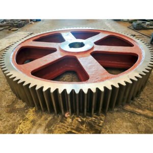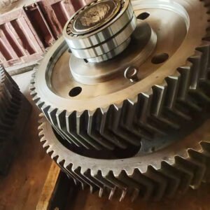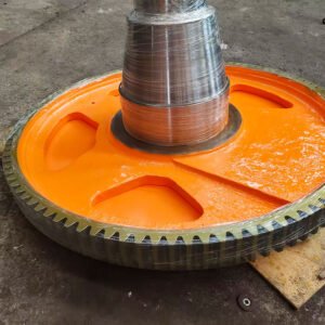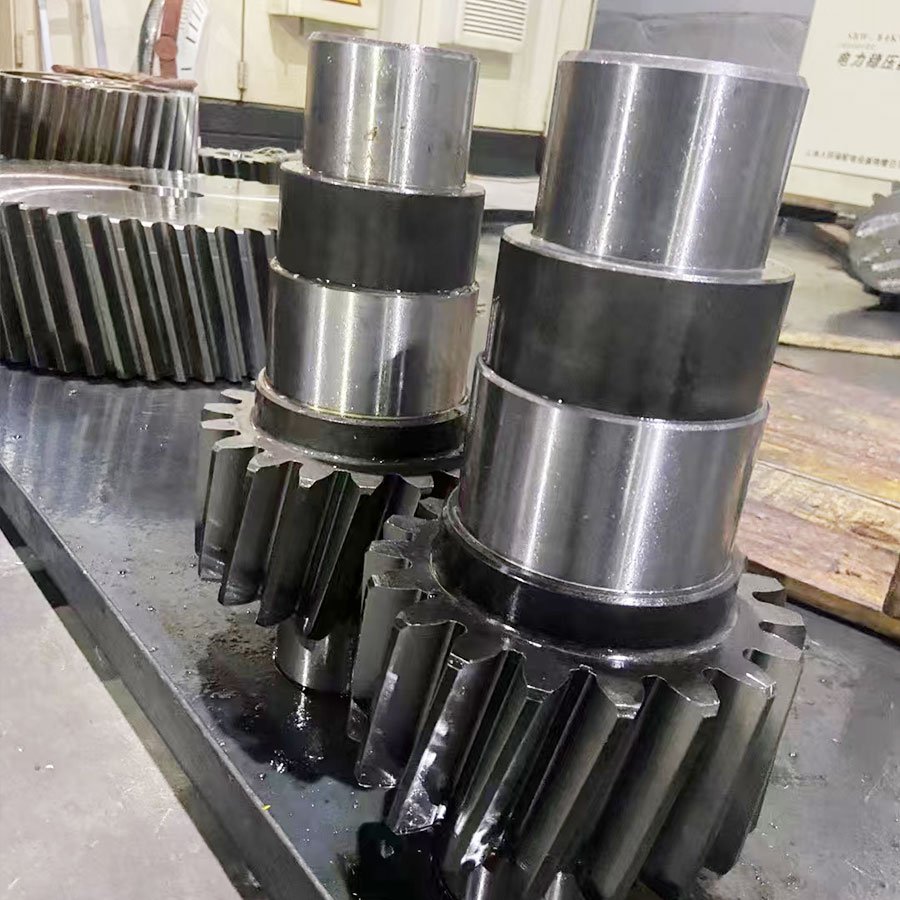
The active gear shaft is the heart of a reducer’s power transmission. For a world-renowned tire manufacturer, we engineered and fabricated 2 units of high-torque helical gear shafts. This project focused on replacing critical drive components to enhance the stability and torsional rigidity of their industrial reducer units.
| Gear Type | Gear Shaft |
| Module | M18 |
| Material | 20CrMnTi |
| Quantity | 2 Units |
| Processing | Gear Hobbing / Gear Grinding |
| Heat Treatment | Quenching & Tempering |
| Tooth Surface Treatment | Carburizing |
| Accuracy Class | DIN 7 |
Why one piece, not a gear on a keyed shaft
A separate gear needs a keyway, and a keyway is where a shaft usually fails first — the corner of the slot concentrates stress exactly where torsional load reverses. Cutting the teeth into the shaft removes that slot, removes the interference fit that has to hold under torque reversal, and lets the outside diameter shrink, which lowers the inertia the motor has to accelerate. The trade-off is unforgiving: one damaged tooth condemns the whole shaft.
Engineering Highlights
Optimized Drive Dynamics: As an active gear shaft, this component must handle intense input speeds and torques. Our helical design ensures smooth engagement with the mating gear, reducing shock loads within the gearbox. Torque does not stay at the nameplate value either: it rises roughly with the reduction ratio, which is why a shaft like this is sized from output torque rather than motor rating. Our engineering mathematics guide walks through that step before a diameter is fixed.
Superior Torsional Strength: Fabricated from 20CrMnTi, the shaft undergoes a rigorous carburizing and grinding process, providing the necessary surface hardness to resist pitting and the core toughness to handle peak torsional stresses.
Master-Level Alignment: With DIN 7 precision grinding, we ensured that the gear profile is perfectly aligned with the shaft axis, significantly reducing heat generation and extending the service life of the entire reducer assembly. Holding that alignment is the demanding part of helical gear fabrication on a shaft: the tooth profile is ground relative to finished journals, so runout at the centres turns straight into profile error.
Ground from the shaft axis, not from the teeth: On a single-piece shaft the datum matters more than the accuracy grade. These are machined between centres and the flanks ground with the journals as reference, so runout between tooth profile and bearing seat stays inside the DIN 7 allowance instead of stacking on top of it. That is what keeps the mesh quiet at input speed — a gear accurate in itself but eccentric to its own bearing journals still runs rough. Carburizing moves a long shaft more than a compact gear, so stock is left on the flanks and removed after hardening, never before.
Conclusion
Both shafts were supplied against the original drawings, with material certificates and dimensional reports included. If you are replacing an active gear shaft in a rubber machinery reducer, send the drawing, the mating gear data, and the operating torque so the shaft and the wheel can be checked as one pair.
FAQ
Q: Can you supply the mating gear as well?
A: Yes. Shaft and mating wheel are normally ordered as a pair, because contact pattern depends on both.
Q: What do you need in order to quote a replacement shaft?
A: The worn part or the original drawing — module, tooth count, helix angle, journal diameters, and keyway or spline detail.