
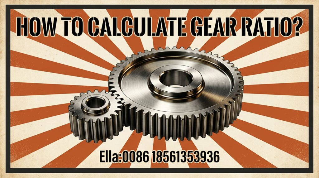
Gear ratio is one of the most fundamental calculations in mechanical power transmission. It determines how rotational speed and torque are transferred from a driving shaft to a driven shaft and is therefore central to the design of gearboxes, reducers, open gear drives, gear-and-pinion systems, and industrial machinery.
For a simple external gear pair, the basic calculation is straightforward:
Gear ratio = Number of teeth on driven gear ÷ Number of teeth on driver gear
However, industrial gear ratio calculation rarely ends with this equation. Engineers must also consider output speed, torque, power, multiple reduction stages, pitch diameter, module, centre distance, gear geometry, efficiency, load capacity, gear quality, lubrication, and operating conditions.
These relationships are particularly important for heavy-duty equipment such as mining mills, cement kilns, sugar mills, rubber machinery, steel equipment, paper machines, marine drives, wind turbines, power-generation equipment, and port cranes.
This guide explains the engineering mathematics behind gear ratio calculation and shows how to apply it to industrial gear systems.
What Is Gear Ratio?
Gear ratio describes the rotational relationship between a driving gear and a driven gear.
For a simple gear pair:
i = N₂ / N₁
Where:
- i = gear ratio
- N₁ = number of teeth on the driving gear
- N₂ = number of teeth on the driven gear
For example, if a 20-tooth pinion drives a 60-tooth gear:
i = 60 / 20 = 3
The system therefore has a 3:1 reduction ratio. The output shaft rotates at one-third of the input speed, while the ideal output torque is approximately three times the input torque before transmission losses.
The same relationship can be expressed using rotational speed:
i = n₁ / n₂
where:
- n₁ = input speed
- n₂ = output speed
Thus:
N₂ / N₁ = n₁ / n₂
Gear Ratio vs. Reduction Ratio
These terms are closely related but should be used carefully.
A reduction ratio greater than 1:1 means the output rotates more slowly than the input. For example, a 5:1 reducer means the input shaft rotates five revolutions for approximately one output revolution.
A speed-increasing gear train reverses the relationship. If a large driving gear drives a smaller driven gear, the output speed increases while available torque decreases.
In engineering documentation, always define which gear is the driver and which is the driven gear. Different manufacturers and industries sometimes express ratios in different conventions.
How to Calculate Gear Ratio
Calculate Gear Ratio from Gear Teeth
For a simple external gear pair:
i = N₂ / N₁
Suppose:
- Driver pinion = 24 teeth
- Driven gear = 96 teeth
Then:
i = 96 / 24 = 4
The gear set provides a 4:1 reduction.
This is normally the most direct method because tooth counts are unambiguous and can be obtained directly from gear drawings or manufacturing documentation.
The corresponding speed relationship is:
n₂ = n₁ × N₁ / N₂
If the input speed is 1,500 rpm:
n₂ = 1,500 × 24 / 96 = 375 rpm
Therefore, the driven shaft rotates at 375 rpm.
Calculate Gear Ratio from Pitch Diameter
Gear ratio can also be calculated from pitch diameters:
i = d₂ / d₁
where:
- d₁ = driver pitch diameter
- d₂ = driven pitch diameter
For spur gears using the same module:
d = m × z
where:
- d = pitch diameter
- m = module
- z = number of teeth
Therefore:
i = (m × z₂) / (m × z₁)
The module cancels:
i = z₂ / z₁
This demonstrates why gear ratio is fundamentally determined by tooth count rather than gear outside diameter.
When calculating ratio from a physical gear, engineers should use the pitch diameter, not the outside or tip diameter.
Calculate Gear Ratio from Input and Output Speed
If the gear teeth are unknown but shaft speeds are available:
i = n₁ / n₂
For example:
- Input speed = 1,500 rpm
- Output speed = 300 rpm
Then:
i = 1,500 / 300 = 5
The required transmission ratio is therefore 5:1.
This method is particularly useful when analyzing an existing gearbox, replacement gear set, or industrial machine where the original gear drawings are unavailable.
Calculate Output Speed and Torque
Gear ratio is not just a speed calculation. It establishes the fundamental speed–torque trade-off of the transmission.
Output Speed
For a reduction drive:
n₂ = n₁ / i
If:
- Input speed = 1,500 rpm
- Gear ratio = 4:1
Then:
n₂ = 1,500 / 4 = 375 rpm
A higher reduction ratio produces a lower output speed.
Output Torque
Ignoring losses, torque is inversely related to rotational speed:
T₂ = T₁ × i
For a real transmission, efficiency must be considered:
T₂ = T₁ × i × η
where η is the transmission efficiency expressed as a decimal.
For example, if the input torque is 1,000 N·m and the ratio is 5:1, the ideal output torque is:
T₂ = 1,000 × 5 = 5,000 N·m
Actual torque will be lower because of gear mesh, bearing, seal, lubrication, and other transmission losses.
Mechanical Advantage
A reduction gear does not create power. It trades rotational speed for torque.
The basic power relationship is:
P = T × ω
where:
- P = power
- T = torque
- ω = angular velocity
Consequently, when speed decreases through a reduction gear, available torque increases correspondingly, subject to efficiency and the load-carrying capacity of the gears and shafts.
This is why high-ratio gearboxes are commonly used where motors operate at relatively high speed but the machine requires high torque at low speed.
Calculate Gear Ratio for Multiple Gear Stages
Industrial gearboxes often require more than one gear stage.
For a multi-stage transmission:
i_total = i₁ × i₂ × i₃ × …
The individual ratios are multiplied, not added.
Compound Gear Trains
Consider a two-stage reducer:
- Stage 1: 20-tooth pinion driving a 60-tooth gear
- Stage 2: 15-tooth pinion driving a 45-tooth gear
Stage ratios are:
i₁ = 60 / 20 = 3
i₂ = 45 / 15 = 3
Therefore:
i_total = 3 × 3 = 9
The complete transmission provides a 9:1 reduction.
If the input speed is 1,800 rpm:
n_out = 1,800 / 9 = 200 rpm
In actual gearbox design, the available ratio is constrained by gear geometry, shaft arrangement, load, allowable tooth forces, efficiency, lubrication, noise, thermal capacity, and packaging.
Multi-Stage Industrial Gearboxes
Large industrial reducers may use several stages to achieve a high overall reduction while keeping individual gear stages within practical design limits.
For each stage, calculate:
- Driver tooth count.
- Driven tooth count.
- Individual stage ratio.
- Intermediate shaft speed.
- Intermediate torque.
- Overall ratio.
- Overall efficiency.
Do not calculate only the final ratio. Intermediate shaft speed and torque are essential for checking gear loads, bearing loads, lubrication requirements, and shaft sizing.
Calculate Gear Ratio in Gear-and-Pinion Systems
Large industrial machinery frequently uses a gear-and-pinion drive, especially where the driven component is too large to integrate into a conventional enclosed gearbox.
Typical examples include large girth gears used on:
- Rotary kilns
- Ball mills
- Industrial dryers
- Sugar mill equipment
- Large process machinery
The pinion is normally the smaller driving gear, while the large gear provides the reduction.
Large Gear and Pinion Ratio
The ratio is:
i = Z_G / Z_P
where:
- Z_G = teeth on the large gear
- Z_P = teeth on the pinion
For example, if a pinion has 24 teeth and the large gear has 120 teeth:
i = 120 / 24 = 5
The large gear therefore rotates at one-fifth of the pinion speed.
For an industrial girth gear, the ratio should be evaluated together with:
- Module
- Number of teeth
- Pitch diameter
- Face width
- Pressure angle
- Helix angle where applicable
- Gear accuracy
- Tooth flank condition
- Material and heat treatment
- Applied torque
- Lubrication
- Alignment
The ratio determines speed, but it does not by itself determine whether the gear can safely transmit the required load.
Gear Ratio Calculations in Major Industries
The mathematics of gear ratio is universal, but the design objective changes significantly by application.
Sugar Mill Gear Ratio
Sugar mill drives often require high torque at relatively low operating speeds.
Gear ratio calculations are used to match the prime mover to mill rolls, crushers, and other driven equipment.
For replacement gears, engineers should verify the original tooth counts, centre distance, module, pressure angle, shaft speed, transmitted power, and direction of rotation before selecting a new ratio.
Rubber Machine Gear Ratio
Rubber machinery such as mixers, mills, extruders, and calenders uses gears to achieve specific roll or screw speeds and torque requirements.
For rubber machinery gears, the ratio should be checked against:
- Motor speed
- Required working speed
- Starting torque
- Peak load
- Duty cycle
- Temperature
- Gearbox efficiency
For heavily loaded applications, the required ratio must be considered together with gear tooth bending and contact strength.
Mining Gear Ratio
Mining machinery frequently requires high torque and low-speed operation.
Applications include:
- Ball mills
- Crushers
- Conveyors
- Hoists
- Heavy-duty process equipment
For large mining gears, the ratio calculation should be combined with load analysis because a correct speed ratio does not guarantee sufficient tooth capacity.
Cement Gear Ratio
Cement plants commonly use large gear-and-pinion systems in rotary kilns, mills, and dryers.
For a kiln drive:
Kiln speed = pinion speed × pinion teeth / girth gear teeth
The selected ratio must provide the required kiln speed while allowing the gear and pinion to transmit the required torque continuously.
Large girth gears also require careful attention to alignment, backlash, tooth contact, lubrication, and installation.
Steel Plant Gear Ratio
Steel production equipment can involve high power, heavy impact loads, and demanding duty cycles.
Gear ratio calculations are relevant to:
- Rolling mill drives
- Conveyors
- Material handling
- Processing equipment
- Auxiliary drives
For these applications, engineers should distinguish between the theoretical ratio and the ratio required under actual operating conditions, including acceleration, transient loading, and service factors.
Marine Gear Ratio
Marine gear systems often reduce relatively high engine or motor speed to the lower rotational speed required by the driven equipment.
For marine applications, ratio calculation must be coordinated with:
- Engine or motor speed
- Propeller or driven-shaft speed
- Torque
- Duty cycle
- Installation arrangement
- Reverse operation where applicable
- Efficiency
The ratio is therefore one part of a broader drivetrain design.
Power Generation Gear Ratio
Power-generation equipment may require precise speed relationships between the prime mover and generator or auxiliary equipment.
For gear-driven systems, engineers must consider both the nominal operating ratio and transient operating conditions.
High-speed applications place additional emphasis on gear accuracy, dynamic behavior, lubrication, balance, vibration, and thermal performance.
Wind Turbine Gear Ratio
Wind turbines typically use gearboxes to convert relatively low rotor speed into a higher generator speed.
The overall ratio can be divided across multiple stages:
i_total = i₁ × i₂ × i₃
Because wind turbines operate under variable loads and speeds, ratio selection must be integrated with gearbox efficiency, bearing loads, gear strength, dynamic behavior, and control requirements.
Paper Machine Gear Ratio
Paper machinery requires coordinated rotational speeds between multiple rolls, cylinders, dryers, and processing sections.
Even a small ratio error can affect line speed and synchronization.
For paper machine gears, the ratio should therefore be checked against the complete drive train rather than treating each gear pair independently.
Port Crane Gear Ratio
Port cranes and heavy-duty lifting systems require substantial torque multiplication and controlled output speed.
A reduction gear may be used between the motor and hoisting mechanism to provide:
- Lower output speed
- Higher output torque
- Controlled lifting movement
Ratio selection must be coordinated with rated load, acceleration, braking, duty classification, gearbox thermal capacity, and mechanical safety requirements.
Gear Ratio, Module, and Gear Geometry
Gear ratio and gear geometry are related but are not interchangeable.
For a cylindrical spur gear:
d = m × z
where m is module and z is tooth count.
Therefore, if the module is fixed, increasing the tooth count increases pitch diameter.
For two externally meshing gears:
a = (d₁ + d₂) / 2
where a is the nominal centre distance.
This means that changing tooth count or module can change the physical arrangement even when the required ratio remains unchanged.
For example, a 4:1 ratio could theoretically be produced with different combinations of tooth counts. The final selection depends on minimum tooth count, centre distance, module, load, manufacturing constraints, tooth geometry, and other design requirements.
For helical gears, engineers must also distinguish between normal module and transverse module when performing geometry calculations. The relevant module definition must therefore be stated clearly on engineering drawings and calculation sheets.
Gear Ratio and Load Capacity
A correct gear ratio does not automatically mean a correct gear design.
Two gear sets can have exactly the same ratio but radically different load-carrying capabilities.
Gear rating calculations may need to consider:
- Transmitted torque
- Tooth bending strength
- Tooth flank/contact strength
- Material
- Heat treatment
- Gear dimensions
- Face width
- Gear accuracy
- Operating speed
- Lubrication
- Load spectrum
- Alignment
- Service conditions
For industrial gears, gear quality classifications such as ISO gear accuracy grades or applicable AGMA quality classifications describe manufacturing accuracy and related geometric characteristics. They should not be confused with the transmission ratio itself.
Similarly, case hardening can improve tooth surface hardness and wear resistance, but it does not change the mathematical gear ratio.
Quick Reference: Gear Ratio Formulas
| Calculation | Formula | Main Use |
|---|---|---|
| Gear ratio | i = Z₂ / Z₁ | Tooth-count calculation |
| Speed ratio | i = n₁ / n₂ | Input/output speed |
| Output speed | n₂ = n₁ / i | Determine driven speed |
| Pitch diameter | d = m × Z | Gear geometry |
| Ratio from diameter | i = d₂ / d₁ | Pitch-diameter calculation |
| Ideal output torque | T₂ = T₁ × i | Torque multiplication |
| Real output torque | T₂ = T₁ × i × η | Torque including efficiency |
| Multi-stage ratio | i_total = i₁ × i₂ × i₃… | Gearbox calculation |
| Centre distance | a = (d₁ + d₂) / 2 | Basic cylindrical gear layout |
| Power relationship | P = T × ω | Speed/torque relationship |
Common Gear Ratio Calculation Mistakes
Several errors repeatedly occur when engineers analyze existing gear systems or specify replacement gears.
1. Using Outside Diameter Instead of Pitch Diameter
The outside diameter is not normally the correct diameter for calculating the transmission ratio.
Use tooth count or pitch diameter.
2. Reversing Driver and Driven Gear
A 20-tooth pinion driving a 60-tooth gear gives a 3:1 reduction.
Reversing the calculation gives 1:3, which represents a different ratio convention.
Always identify the input and output shafts.
3. Adding Multi-Stage Ratios
For a multi-stage gearbox, ratios are multiplied:
i_total = i₁ × i₂
They are not added.
4. Ignoring Efficiency
Ideal torque calculations assume no losses. Actual output torque depends on transmission efficiency.
5. Assuming Ratio Determines Gear Strength
Ratio only defines the kinematic relationship. It does not determine tooth bending strength, contact strength, shaft strength, bearing capacity, or service life.
6. Ignoring Module and Geometry
Two gears can theoretically have the same ratio but cannot necessarily replace one another.
Module, pressure angle, tooth form, helix angle, face width, centre distance, and other geometry must also match the application.
How to Select the Correct Gear Ratio
For an industrial machine, use the following engineering sequence:
- Determine required output speed.
- Determine motor or input speed.
- Calculate the required overall ratio.
- Determine required output torque.
- Allow for transmission efficiency.
- Divide the ratio across appropriate gear stages if necessary.
- Select tooth counts and module based on geometry and load.
- Check gear bending and contact strength.
- Check shaft, bearing, lubrication, and thermal requirements.
- Verify gear accuracy, alignment, backlash, and operating conditions.
For a replacement industrial gear, the safest approach is to obtain the original gear drawing or collect complete dimensional and operating information before manufacturing.
Important information includes tooth count, module, pitch diameter, pressure angle, face width, bore, keyway or connection details, gear type, helix angle where applicable, material, heat treatment, operating speed, transmitted power or torque, and centre distance.
Conclusion
Gear ratio calculation begins with a simple relationship between tooth counts:
i = Z₂ / Z₁
From this fundamental equation, engineers can calculate output speed, ideal torque multiplication, pitch diameter relationships, and the overall ratio of compound gear trains.
However, industrial gear engineering requires more than calculating a ratio. For mining gears, cement girth gears, sugar mill gears, rubber machinery gears, steel plant drives, marine gear systems, wind turbine gearboxes, paper machine drives, power equipment, and port cranes, the ratio must be integrated with gear geometry, load capacity, efficiency, materials, heat treatment, gear accuracy, lubrication, alignment, and operating conditions.
The most important principle is simple: gear ratio determines the kinematic relationship; complete gear design determines whether that relationship can be transmitted safely and reliably under the actual machine load.
For large industrial gears and custom gear-and-pinion systems, ratio calculation should therefore be treated as the first step of engineering verification—not the final design calculation.
Frequently Asked Questions
1. What is the basic formula for calculating gear ratio?
For a simple external gear pair:
Gear ratio = driven gear teeth ÷ driving gear teeth
If a 20-tooth pinion drives a 60-tooth gear, the ratio is 3:1.
2. How do I calculate gear ratio from RPM?
Use:
i = input speed ÷ output speed
For example, if the input shaft runs at 1,500 rpm and the output shaft runs at 300 rpm, the reduction ratio is 5:1.
3. How do I calculate output RPM from a gear ratio?
Use:
Output RPM = Input RPM ÷ Gear Ratio
For a 4:1 reduction with an input speed of 1,200 rpm:
1,200 ÷ 4 = 300 rpm
4. How do I calculate torque from gear ratio?
For an ideal transmission:
Output torque = Input torque × Gear ratio
For an actual system, include efficiency:
Output torque = Input torque × Gear ratio × Efficiency
5. How do I calculate the ratio of a large gear and pinion?
Divide the number of teeth on the large gear by the number of teeth on the pinion:
i = Z_large gear / Z_pinion
The same ratio can be obtained from their pitch diameters when the gears are correctly matched.
6. Does module affect gear ratio?
Module does not directly determine the ratio. For a compatible gear pair:
d = m × Z
Because module appears in both pitch diameters, it cancels when calculating the ratio. However, module strongly affects the physical size and load-carrying capability of the gear.
7. Does a higher gear ratio always mean more torque?
A higher reduction ratio provides greater theoretical torque multiplication and lower output speed. However, actual torque is limited by efficiency and the mechanical strength of the gears, shafts, bearings, and other components.
8. How do I calculate the ratio of a multi-stage gearbox?
Multiply the individual stage ratios:
i_total = i₁ × i₂ × i₃
For example, three stages of 2:1, 3:1, and 4:1 produce an overall ratio of:
2 × 3 × 4 = 24:1
9. Do AGMA or ISO gear quality grades change the gear ratio?
No. Gear accuracy classifications such as applicable AGMA quality classifications or ISO gear accuracy grades describe manufacturing accuracy and related geometric characteristics. They do not change the fundamental tooth-count ratio.
10. What information is needed to calculate or replace an industrial gear ratio?
At minimum, identify the driver and driven tooth counts or pitch diameters and the input/output speeds. For an actual replacement gear, engineers should also verify module, pressure angle, face width, gear type, helix angle where applicable, centre distance, material, heat treatment, bore and connection details, operating torque, speed, lubrication, and load conditions.