
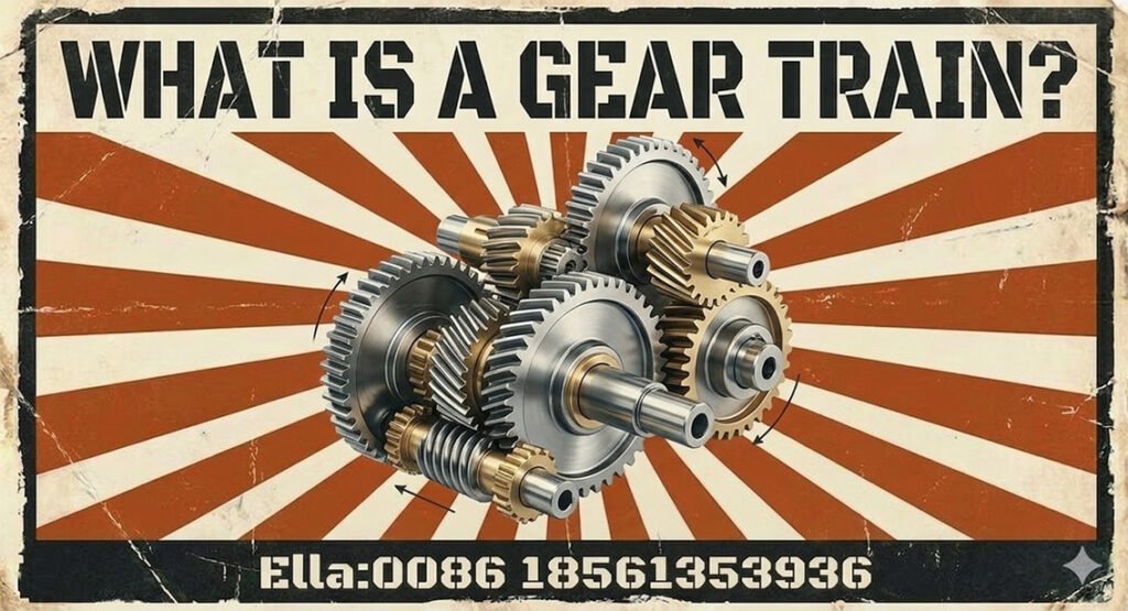
A gear train is a mechanical transmission system that uses two or more meshing gears to transfer rotational motion and power between shafts. By selecting the appropriate gear arrangement and tooth counts, engineers can control output speed, increase or decrease torque, change the direction of rotation, and distribute power between multiple outputs.
Gear trains are used throughout industrial machinery, from compact precision gearboxes to heavy-duty drives in mining mills, cement kilns, sugar mills, steel plants, paper machines, marine equipment, wind turbines, and port cranes. In high-load applications, reliable performance depends not only on the gear ratio but also on tooth geometry, material properties, lubrication, alignment, manufacturing accuracy, and operating conditions.
This guide explains how gear trains work, compares the main types, shows how to calculate gear ratios, and outlines the engineering considerations involved in selecting, manufacturing, and maintaining industrial gear transmission systems.
1. What Is a Gear Train?
A gear train is an arrangement of two or more gears that transmit rotary motion through direct tooth engagement. The gear receiving power from the input shaft is the driving gear, while the gear receiving motion is the driven gear. Additional gears may connect stages, change rotation direction, or provide more complex speed and torque relationships.
Several terms are fundamental to gear train design:
- Pinion: The smaller gear in a meshing pair, although the term can also refer to a gear’s role in a particular mechanism.
- Gear ratio: The relationship between the input and output rotational speeds, commonly determined from the tooth counts of the meshing gears.
- Idler gear: An intermediate gear that transmits motion between other gears without changing the overall ratio magnitude in a simple external gear train.
- Module: A metric measure of gear tooth size, defined as reference diameter divided by tooth count for a standard cylindrical gear.
- Pitch diameter: The reference diameter used to define the rolling relationship between mating gears.
A gear train may consist of a single gear pair or multiple stages arranged in series or in a more complex configuration. In industrial gear drives, the complete system may include gears, shafts, bearings, a housing, lubrication equipment, and seals.
The distinction between a gear train and a gearbox is useful: a gear train describes the gear arrangement and its transmission relationships, while a gearbox is the mechanical assembly that houses and supports the transmission components.
2. How Does a Gear Train Work?
When two gears mesh, the teeth transmit force at their contact surfaces. The relative pitch diameters and tooth counts determine their rotational relationship. For a pair of compatible external cylindrical gears, the smaller gear generally rotates faster than the larger gear, while the larger gear delivers greater torque when losses are neglected.
For an ideal gear pair:
- Speed: Output speed decreases as the driven gear’s tooth count increases relative to the driving gear.
- Torque: Output torque increases approximately in proportion to the reduction ratio, before accounting for losses.
- Direction: Two externally meshing gears rotate in opposite directions. An internal gear mesh produces the same rotational direction between the gears.
- Power: Mechanical power is related to torque and angular speed. A gear train changes the torque-speed relationship but does not create power.
In a real transmission, friction, bearing losses, lubricant churning, and other effects reduce output power. Efficiency depends on the gear type, number of stages, load, speed, lubrication, and operating condition.
For heavy-duty machinery, gear teeth must also withstand repeated contact stress and bending stress. Shock loads, misalignment, inadequate lubrication, or excessive deflection can reduce service life even when the nominal gear ratio is correct.
3. Main Types of Gear Trains
Different gear train configurations address different requirements for ratio, shaft arrangement, space, torque capacity, and power distribution.
3.1 Simple Gear Train
A simple gear train has one gear mounted on each shaft, with adjacent gears meshing in sequence. It is straightforward to design and is suitable for mechanisms requiring a moderate ratio or a change in rotational direction.
An idler gear may be added between the input and output gears. The idler changes the number of external meshes and therefore the output direction, but it does not change the overall ratio magnitude when the first and last gears determine the ratio.
Simple gear trains are common in basic machinery drives and mechanisms where the required ratio can be achieved without compound stages.
3.2 Compound Gear Train
A compound gear train has at least one shaft carrying two or more gears rigidly connected to rotate together. Each gear on that shaft can drive a different gear in the next stage, allowing the overall ratio to be much larger or smaller than the ratio of a single gear pair.
Compound arrangements are useful when machinery requires substantial speed reduction within a limited space. They are found in industrial reducers and multi-stage drives serving mining equipment, steel-processing machinery, material handling systems, and other high-torque applications.
Designers must consider cumulative losses, shaft loads, bearing reactions, housing stiffness, and the effects of manufacturing tolerances across all stages.
3.3 Reverted Gear Train
A reverted gear train is a compound gear train in which the input and output shafts are coaxial. This arrangement is useful when the transmission must provide a speed change while keeping the input and output on the same axis.
The geometry must satisfy the center-distance requirements of both gear meshes. For standard external cylindrical gear pairs sharing the same center distance, the relevant pitch-diameter relationships constrain the tooth counts and gear sizes.
Reverted arrangements are used in selected compact drives and mechanisms where coaxial shaft layout is a key packaging requirement.
3.4 Planetary Gear Train
A planetary, or epicyclic, gear train typically contains a central sun gear, surrounding planet gears, a planet carrier, and an internal ring gear. The planets rotate on their own axes while orbiting around the sun.
Its principal advantage is a high torque capacity relative to its package size, particularly when load is shared among multiple planets. Depending on which member is fixed, driven, or used as the output, the same basic arrangement can provide different ratios and operating modes.
Planetary gear trains are widely used in industrial reducers, mobile equipment, wind turbine gearboxes, and heavy-duty hoisting or slewing drives. Their performance depends on accurate geometry, effective load sharing, suitable bearing arrangements, and adequate lubrication.
3.5 Gearboxes and Multi-Stage Transmission Systems
Many industrial gearboxes combine several gear pairs in a single housing. A reducer may use parallel-shaft helical gears, bevel gears to change shaft direction, planetary stages for compact high reduction, or combinations of these arrangements.
The choice depends on required input and output speeds, torque, shaft orientation, installation space, efficiency, service conditions, and maintenance requirements. A large open gear drive—such as the girth gear and pinion arrangement used on some mills and kilns—differs from an enclosed gearbox, even though both transmit power through meshing gears.
4. How to Calculate a Gear Train Ratio
Gear ratio calculation establishes the relationship between input and output speed. For a simple gear pair, the ratio magnitude is determined by the tooth counts, assuming compatible gears operating without tooth slip.
4.1 Simple Gear Ratio
For a pair of meshing gears, define the reduction ratio as input speed divided by output speed:
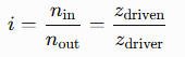
Where:
- i is the reduction ratio.
- nin is input rotational speed.
- nout is output rotational speed.
- zdriver and zdriven are the respective tooth counts.
For example, if the driving gear has 20 teeth and the driven gear has 60 teeth, the reduction ratio is 3:1. The output speed is one-third of the input speed, and ideal output torque is approximately three times the input torque before transmission losses.
This ratio convention should be stated clearly because some references define gear ratio using output speed divided by input speed.
4.2 Compound Gear Train Ratio
For a compound train, calculate the ratio of each meshing stage and multiply the stage ratios to obtain the overall reduction ratio:

The gears fixed to the same shaft rotate at the same speed, linking the stages. The overall ratio can therefore be much greater than the ratio of any individual pair.
When calculating direction, count the external meshes: each external mesh reverses rotation, while an internal mesh does not. Ratio magnitude and rotation direction should be treated as separate parts of the calculation.
4.3 Planetary Gear Train Ratio
Planetary gear trains require additional care because the carrier itself rotates. The ratio depends on the tooth counts and on which member is the input, output, and stationary member.
For a simple planetary set with a sun gear, an internal ring gear, and a carrier, the relationship between the sun speed, ring speed, and carrier speed is:
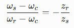
Here, ws, wc, and wr are the angular speeds of the sun, ring, and carrier, respectively; zs and zr are the sun and ring tooth counts. The equation assumes a conventional simple planetary arrangement with compatible geometry.
To calculate a specific planetary ratio, substitute the known speeds and the stationary member’s speed, then solve for the required output. Always identify the fixed member before using a ratio formula.
5. Key Engineering Parameters in Gear Train Design
A suitable gear train must meet the required kinematic relationship while withstanding the loads, speeds, temperatures, and operating cycles imposed by the machine.
5.1 Gear Geometry and Tooth Parameters
Gear geometry determines whether components mesh correctly and how loads are transmitted. Important parameters include:
- Module and tooth count: For a standard metric cylindrical gear, the reference diameter is related to module and tooth count by d=mz. Mating gears must have compatible tooth geometry; matching module alone does not guarantee compatibility.
- Pressure angle and tooth profile: These affect tooth contact, force transmission, and bending strength. Mating gears must use compatible profiles and pressure-angle conventions.
- Helix angle: For helical gears, helix angle influences contact ratio, axial force, noise, and load capacity.
- Center distance and backlash: Incorrect center distance or unsuitable backlash can contribute to interference, poor contact, excessive noise, or thermal problems.
- Shaft arrangement: Parallel, intersecting, and skew shaft configurations require different gear types and geometric calculations.
Spur and helical gears commonly transmit power between parallel shafts, while bevel gears serve intersecting shafts and worm gearing commonly serves skew shafts. Hypoid gearing also uses offset, non-intersecting axes. The gear type must match the required shaft geometry and operating conditions.
5.2 Torque, Speed, Power, and Operating Loads
Gear train sizing begins with input power, speed, output requirements, and the duty cycle. For rotational motion, power is related to torque and angular speed:
P=Tw
Where P is power, T is torque, and w is angular speed. In a reduction drive, output speed decreases while available output torque increases, subject to transmission efficiency.
Engineers should evaluate more than nominal power. Relevant conditions include:
- Starting, stopping, reversing, and frequent load changes.
- Shock loads and torque peaks during jams or process disturbances.
- Continuous operation, intermittent duty, and required service life.
- Shaft deflection, bearing displacement, housing deformation, and alignment changes.
- Thermal limits, lubrication conditions, and heat dissipation.
A service factor may be used within an appropriate rating method to account for application severity, but it should not replace a proper load assessment. For critical industrial drives, tooth-root bending strength, flank contact strength, scuffing resistance, and other applicable failure modes should be evaluated using a suitable design methodology.
5.3 Materials, Heat Treatment, and Manufacturing Accuracy
Gear material and heat treatment influence load capacity, wear resistance, toughness, and resistance to fatigue. Selection depends on tooth size, transmitted torque, impact loading, manufacturing route, and the consequences of failure.
Common choices include:
- Through-hardened steels: Used where a balance of strength, toughness, and manufacturing practicality is appropriate.
- Case-hardened alloy steels: Carburizing and subsequent hardening can produce a hard wear-resistant surface with a tougher core, making this approach suitable for many highly loaded gear applications.
- Other material and treatment options: Selected according to load, speed, environment, size, and the required combination of surface and core properties.
Manufacturing accuracy also matters. Tooth spacing errors, runout, profile deviations, lead deviations, and surface finish can influence load distribution, vibration, noise, and fatigue life. Inspection requirements should be based on the gear’s function and the applicable ISO or AGMA rating and accuracy framework, rather than assigning a grade without considering the specific gear type and standard.
For large industrial gears, the quality of the complete transmission system is equally important. A correctly manufactured gear can still fail prematurely if its mating component, shaft support, lubrication system, or alignment is unsuitable.
6. Industrial Applications of Gear Trains
Gear train configurations vary with the machinery’s torque demand, operating speed, installation space, and production process. The following examples illustrate where different transmission arrangements are used.
6.1 Mining and Cement Equipment
Mining and cement plants use gear trains in crushers, conveyors, grinding mills, and rotary kiln drives. Large mills may employ an open gear drive comprising a pinion and a large girth gear, while other equipment uses enclosed multi-stage reducers.
These applications commonly involve high torque, abrasive dust, heavy operating loads, and difficult maintenance access. Gear train design should address load fluctuations, pinion alignment, foundation movement, lubrication delivery, tooth contact patterns, and inspection access.
A girth gear should not be treated as interchangeable with a complete gearbox: it is a large gear component within a particular drive arrangement, whereas a gearbox contains the supported gear stages and related components.
6.2 Sugar Mills and Rubber Machinery
Sugar mills use gear transmission systems in cane preparation, crushing, milling, and associated process equipment. Large bull gears and other reduction gears may be used where low speed and high torque are required.
Rubber machinery—including internal mixers, open mixing mills, calenders, and extruders—may use compound or multi-stage gear trains to deliver controlled speed and torque. Different processes impose different load patterns: mixing and milling can produce substantial torque variation, while extrusion drives require stable operation under process load.
Material selection, tooth strength, heat treatment, shaft stiffness, and lubrication must be considered alongside the transmission ratio. Replacement gears should be matched to the existing geometry and operating conditions rather than selected by external dimensions alone.
6.3 Steel Plants and Paper Mills
Steel-processing machinery uses gear trains in rolling mills, coilers, uncoilers, conveyors, and other production equipment. Drives may experience high torque, repeated starts and stops, reversing loads, or strict synchronization requirements.
Paper manufacturing equipment uses gear transmission systems in pulpers, refiners, dryer sections, calenders, rewinders, and related machinery. Depending on the machine, the design may prioritize speed control, reliable continuous operation, load sharing, or synchronization between sections.
For both industries, backlash, torsional stiffness, vibration, and alignment can affect process stability. Maintenance planning should include inspection of tooth surfaces, bearings, lubricant condition, and shaft interfaces.
6.4 Marine, Power Generation, and Wind Energy
Marine reduction gearboxes convert high-speed prime-mover output into a suitable speed for propulsion or other driven equipment. Depending on the design, they may use parallel-axis, bevel, planetary, or combined gear arrangements. Reliability, lubrication, vibration, alignment, and load reversals are important considerations.
Wind turbine gearboxes commonly use multi-stage transmissions, often including planetary stages, to adapt rotor speed to generator requirements. Gear train design must account for variable operating conditions, torque fluctuations, structural deflection, lubrication, and fatigue over a long service life.
Power-generation equipment more broadly may use gear trains where a particular speed conversion, shaft arrangement, or torque relationship is required. The appropriate configuration depends on the machine’s function rather than on the industry label alone.
6.5 Port Cranes and Heavy Material Handling
Port cranes and other heavy material-handling equipment use gear trains in hoisting, luffing, trolley travel, and slewing drives. Compact planetary reducers may be suitable where high torque is required in a restricted installation space, while parallel-shaft arrangements can suit other layouts.
Designers should consider load cycles, starting torque, braking events, shock loads, gear and bearing life, and the effects of repeated operation. For slewing drives in particular, the complete assembly—including the gear mesh, supporting structure, bearings, and mounting interfaces—must be evaluated as a system.
7. Common Gear Train Failure Modes and Prevention
Gear train failures can result from excessive loads, unsuitable materials, poor lubrication, misalignment, manufacturing defects, or operating conditions outside the design envelope. Identifying the failure mechanism is essential before choosing a corrective action.
| Failure mode | Typical contributing factors | Practical prevention |
|---|---|---|
| Pitting or surface fatigue | Repeated contact stress, inadequate load capacity, poor lubrication, or unsuitable surface properties | Verify contact-stress rating, lubricant suitability, tooth contact, and material treatment |
| Tooth-root cracking or breakage | Excessive bending stress, shock loading, stress concentrations, or material defects | Check bending strength, load peaks, tooth geometry, material quality, and shaft support |
| Scuffing or scoring | Lubrication film breakdown, high sliding speed, excessive temperature, or unsuitable lubricant | Review lubricant viscosity and supply, operating temperature, surface condition, and loading |
| Uneven tooth wear | Misalignment, deflection, incorrect contact pattern, contamination, or poor lubrication | Inspect alignment, bearings, foundation and housing stiffness, lubricant cleanliness, and tooth contact |
| Noise and vibration | Tooth errors, backlash problems, damaged teeth, eccentricity, or dynamic resonance | Inspect tooth geometry, runout, bearings, alignment, lubrication, and vibration trends |
Maintenance should combine visual inspection with operating data where available. Changes in vibration, temperature, lubricant condition, noise, or tooth contact can indicate developing problems, but none should be interpreted in isolation.
For a failed large gear, replacing the damaged component without investigating the underlying cause can lead to repeated failure. The investigation should examine the mating gear, shafts, bearings, foundation, lubrication system, installation records, and actual load history.
8. How to Select the Right Gear Train or Industrial Gearbox
Selecting a gear train is a system-level engineering decision. The most suitable arrangement is the one that meets the required performance and service-life targets within the machine’s physical and operating constraints.
Start by documenting:
- Input and output requirements: Power, speed, torque, reduction ratio, and required direction of rotation.
- Duty conditions: Operating hours, starts and stops, reversals, shock loads, temperature, and expected service life.
- Installation constraints: Shaft orientation, center distance, available space, mounting arrangement, and interfaces with connected equipment.
- Performance requirements: Efficiency, noise, vibration, backlash, positional accuracy, and thermal limits.
- Maintenance conditions: Lubrication method, inspection access, spare-part availability, and repair requirements.
Next, evaluate gear geometry, material, heat treatment, tooth strength, shaft and bearing loads, housing stiffness, and manufacturing accuracy. For heavy-duty drives, the assessment should reflect actual service loads rather than relying exclusively on nominal motor power.
When comparing suppliers, ask for evidence that the proposed transmission is suitable for the application. Relevant information may include the design basis, material and heat-treatment documentation, inspection records, gear quality requirements, lubrication recommendations, and experience with similar operating conditions.
For a custom gear or replacement gear, provide existing drawings where available and confirm critical dimensions and tooth geometry. If original drawings are unavailable, the supplier may need to inspect the component and establish its geometry before manufacturing.
9. Gear Train Manufacturing, Inspection, and Replacement
9.1 Manufacturing and Quality Inspection
Industrial gear manufacturing may involve blank production, machining, tooth cutting or generating, heat treatment, and finishing operations such as grinding when required by the design. The sequence depends on gear size, material, tooth geometry, production method, and accuracy requirements.
Inspection should be aligned with the component’s function and drawing requirements. Depending on the application, it may include:
- Tooth count, module or applicable tooth-size specification, reference dimensions, and critical mounting dimensions.
- Tooth profile, lead, pitch-related deviations, runout, and other specified accuracy characteristics.
- Hardness and verification of heat-treatment requirements.
- Surface condition, cracks, and other relevant material or manufacturing defects.
- Trial assembly, contact-pattern checks, and verification of mating components where appropriate.
Applicable standards should be selected for the gear type and the intended rating or inspection activity. ISO and AGMA documents cover different aspects of gear geometry, accuracy, rating, and terminology; they should be applied according to their scope rather than treated as interchangeable labels.
9.2 Replacing or Customizing an Industrial Gear
A replacement gear must match the required geometry and transmission function—not merely the old component’s outside diameter.
Useful information for a gear manufacturer includes:
- Gear type, tooth count, module or diametral pitch, pressure angle, and helix angle where applicable.
- Reference dimensions, face width, bore, shaft interface, keyway, splines, mounting holes, and other critical features.
- Material, heat treatment, hardness requirements, and specified gear accuracy.
- Mating gear details, center distance, rotation direction, operating speed, torque, and duty cycle.
- Lubrication conditions, environmental exposure, failure history, and any available drawings or inspection measurements.
For large module and large diameter gears, the feasibility of manufacturing and inspection should be confirmed early. Blank capacity, tooth-cutting equipment, heat-treatment capability, finishing methods, lifting and handling arrangements, and measurement equipment can all affect the achievable design and delivery plan.
Where a gear is being replaced after failure, the supplier should also understand why the original component failed. A geometrically correct replacement may not solve problems caused by misalignment, inadequate lubrication, excessive loading, or a defective supporting structure.
10. Frequently Asked Questions About Gear Trains
10.1 What is a gear train used for?
A gear train transmits rotational power while controlling speed, torque, direction, or the relationship between multiple rotating components. Common uses include industrial reducers, machine drives, cranes, mills, and wind turbine gearboxes.
10.2 What are the main types of gear trains?
The main configurations include simple, compound, reverted, and planetary gear trains. Industrial gearboxes may combine multiple stages or different gear types to meet speed, torque, shaft-layout, and space requirements.
10.3 How do you calculate a gear train ratio?
For a simple external gear pair, divide the driven gear’s tooth count by the driving gear’s tooth count to obtain the reduction ratio. For a compound train, multiply the ratios of the individual stages. Planetary gear trains require a formula that accounts for the sun, ring, and carrier speeds and identifies which member is fixed.
10.4 What is the difference between a gear train and a gearbox?
A gear train is the arrangement of gears that establishes the transmission relationship. A gearbox is the assembly that supports and encloses the gear train, typically including shafts, bearings, housing, seals, and lubrication provisions.
10.5 Does an idler gear change the gear ratio?
In a simple gear train with fixed-axis external gears, an idler does not change the magnitude of the overall ratio determined by the first and last gears. It changes the direction relationship by adding another mesh. More complex arrangements must be evaluated from their actual gear connections.
10.6 What is the difference between a compound gear train and a planetary gear train?
A compound gear train uses multiple gears, with at least one shaft carrying gears rigidly connected together, to multiply stage ratios. A planetary train uses sun and planet gears, typically with an internal ring gear and a carrier, enabling compact layouts and different ratios depending on which member is fixed or driven.
10.7 How do you calculate the output torque of a gear train?
For a reduction ratio defined as input speed divided by output speed, approximate output torque as input torque multiplied by the ratio and overall transmission efficiency:
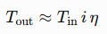
This relationship estimates steady-state torque. Actual design must also consider load peaks, dynamic effects, gear and shaft strength, and the limitations of bearings and other components.
10.8 Which materials are suitable for heavy-duty gear trains?
Through-hardened steels and case-hardened alloy steels are common choices, but the best material depends on load, tooth size, impact conditions, fatigue requirements, manufacturing method, and cost. Material selection should be coordinated with the heat-treatment process and the required surface and core properties.
10.9 What causes gear train failure?
Common causes include tooth bending overload, contact fatigue, scuffing, misalignment, inadequate lubrication, contamination, manufacturing defects, and excessive dynamic loading. Effective troubleshooting identifies the underlying cause before a damaged gear is replaced.
10.10 How do you choose an industrial gear train manufacturer?
Assess the manufacturer’s ability to understand the operating conditions, engineer the required transmission, manufacture the specified gear geometry, control materials and heat treatment, inspect critical features, and support installation or replacement. For large industrial gears, verify equipment capacity and inspection capability for the actual component size and requirements.
A reliable gear train is more than a collection of gears with the correct tooth counts. Its performance depends on the interaction of geometry, materials, load rating, manufacturing accuracy, lubrication, alignment, and the surrounding mechanical system. For industrial applications, coordinating these factors during selection and design is the foundation of dependable power transmission.