

Bevel gears are essential mechanical components for transmitting power between intersecting shafts. They are widely used in industrial gearboxes, machine tools, material-handling equipment, and specialized drive systems where the direction of rotation must change without relying on a belt, chain, or additional transmission stage.
Selecting the right bevel gear requires more than matching tooth counts and shaft angles. Engineers must evaluate gear geometry, torque, speed, tooth contact, material properties, lubrication, mounting accuracy, and operating conditions. These factors determine load capacity, transmission efficiency, noise, service life, and maintenance requirements.
This guide explains how bevel gears work, compares their main types, reviews critical design parameters, and outlines practical selection and maintenance considerations across major industrial sectors.
1. What Is a Bevel Gear?
A bevel gear is a gear with teeth arranged on a conical pitch surface. It transmits rotary motion and torque between shafts whose axes typically intersect. A 90-degree shaft arrangement is common, although bevel gears can be designed for other shaft angles.
Unlike spur and helical gears, which commonly transmit power between parallel shafts, bevel gears change the direction of the transmission path. They are therefore useful in right-angle gearboxes, differential mechanisms, and specialized industrial drive assemblies.
Key geometric terms include:
- Pitch cone: The imaginary cone used to define the rolling geometry of a bevel gear.
- Pitch angle: The angle between the gear axis and the generator of its pitch cone.
- Pitch diameter: A reference dimension associated with the gear’s pitch geometry, used in design and transmission calculations.
- Module: A metric measure of tooth size. For bevel gears, module must be interpreted at the specified reference position, commonly the large end for conventional straight bevel gear calculations.
- Shaft angle: The angle between the axes of the mating gears.
A bevel gear pair must be designed as a coordinated system. Tooth geometry, pitch cones, mounting distances, and shaft positioning must be compatible to achieve the intended contact pattern and load distribution.
2. How Do Bevel Gears Work?
When two correctly matched bevel gears mesh, their teeth transmit force across the contact surfaces, causing the driven gear to rotate. The conical geometry allows the transmission to operate between intersecting shaft axes.
The fundamental speed relationship for a conventional external gear pair is determined by tooth count:

Here, n1 and n2 are the rotational speeds of the driving and driven gears, while z1 and z2 are their respective tooth counts.
For example, when a smaller driving gear meshes with a larger driven gear, the driven gear rotates more slowly and can deliver higher torque, subject to transmission losses. The ideal torque relationship is inversely proportional to speed, while actual output depends on efficiency.
Bevel gears also generate forces that affect shaft and bearing design. Depending on tooth geometry and operating conditions, these include tangential, radial, and axial force components. Spiral bevel gears, in particular, require careful consideration of axial thrust and bearing arrangements.
Reliable operation depends on:
- Correct mounting distances and shaft alignment.
- Appropriate backlash and tooth contact.
- Adequate lubrication and heat dissipation.
- Sufficient tooth-root and contact-fatigue strength.
- Shaft and bearing stiffness under operating loads.
Even a well-manufactured gear can fail prematurely if the assembled transmission does not maintain the intended geometry under load.
3. What Are the Main Types of Bevel Gears?
3.1 Straight Bevel Gears
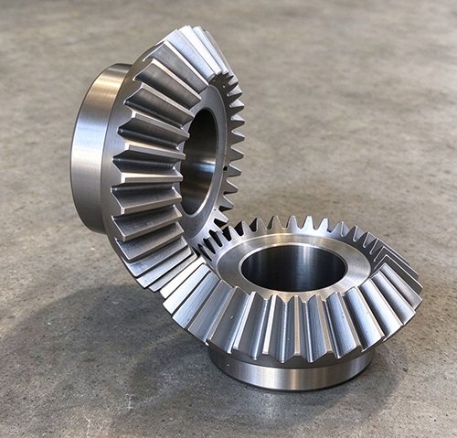
Straight bevel gears have teeth that extend generally along the direction of the pitch cone elements. Their tooth geometry is relatively straightforward compared with more complex curved-tooth designs.
Typical advantages include:
- Relatively simple geometry and established manufacturing methods.
- Suitability for many low- to moderate-speed right-angle drives.
- Practical use in compact industrial mechanisms and conventional gearboxes.
However, straight bevel gears may produce more noticeable engagement noise and vibration than well-designed spiral bevel gears in comparable high-speed applications. Their suitability depends on the required load capacity, operating speed, accuracy, and manufacturing quality.
3.2 Spiral Bevel Gears
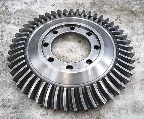
Spiral bevel gears have curved teeth arranged at a spiral angle. Their engagement generally develops progressively, which can improve smoothness and reduce noise and vibration compared with comparable straight bevel gears.
They are frequently selected for demanding transmissions requiring smooth operation and substantial power density. Their design and manufacture are more complex, and performance depends heavily on tooth geometry, contact pattern, mounting accuracy, and lubrication.
Engineers must also account for the axial and radial forces generated by the selected geometry when specifying shafts and bearings.
3.3 Zerol Bevel Gears
Zerol bevel gears use curved teeth with a nominal spiral angle of approximately zero at the reference position. They combine curved-tooth geometry with characteristics closer to straight bevel gearing.
They may be suitable where a design requires curved teeth but has specific constraints on spiral angle or force behavior. Actual performance must be assessed using the manufacturer’s gear geometry and load-rating method rather than assuming that Zerol gears behave identically to either straight or conventional spiral bevel gears.
3.4 Hypoid Gears vs. Bevel Gears
Hypoid gears resemble spiral bevel gears but have offset, non-intersecting shaft axes. This offset can support compact packaging and different transmission arrangements.
The principal distinctions are:
- Conventional bevel gears: Designed primarily for intersecting shaft axes.
- Hypoid gears: Designed for offset shaft axes, with substantial sliding action along the tooth surfaces.
Hypoid gearing requires careful lubricant selection because sliding contact can create demanding friction and surface-temperature conditions. Hypoid gears should not be treated as ordinary intersecting-axis bevel gears when specifying geometry or calculating load capacity.
4. Bevel Gear Design: Key Parameters Engineers Need to Know
Bevel gear design requires coordinated consideration of tooth geometry, loading, materials, manufacturing capability, and assembly conditions. A nominal gear ratio alone is not sufficient to establish whether a gear pair can safely transmit the required power.
4.1 Module, Pitch Diameter, and Tooth Count
Module,m, expresses tooth size in metric gear design. For a conventional straight bevel gear, the relationship between the large-end reference pitch diameter, module, and tooth count is:
d=mz
where d is the reference pitch diameter and z is the number of teeth. This simplified relationship must be applied using the correct reference position and applicable bevel gear geometry.
Important design considerations include:
- Module and tooth count: Influence tooth dimensions, gear size, and load capacity.
- Pitch diameter: Helps establish transmission geometry and the spatial arrangement of the gear pair.
- Face width: Affects the available tooth contact area and load distribution.
- Gear ratio: Determines the required relative tooth counts and rotational speeds.
- Mounting dimensions: Control the position of the gears relative to one another and are essential to correct meshing.
For spiral bevel and hypoid gears, engineers must use the appropriate geometric definitions and design procedures rather than applying cylindrical gear equations indiscriminately.
4.2 Shaft Angle and Gear Ratio
The shaft angle is the angle between the rotational axes of the mating gears. A right-angle arrangement is common in industrial gearboxes, but the design must accommodate the actual shaft geometry required by the machine.
For an external gear pair, the magnitude of the speed ratio is determined by the tooth-count ratio:

Here, i represents the reduction ratio when the driving gear is gear 1 and the driven gear is gear 2.
A 1:1 ratio produces equal rotational speed magnitudes, while a larger driven gear tooth count produces speed reduction. The actual torque capacity must be verified against tooth bending strength, contact stress, shaft and bearing loads, and the operating duty cycle.
4.3 Materials, Heat Treatment, and Gear Quality
Material selection depends on transmitted torque, rotational speed, shock loading, required service life, manufacturing route, and environmental conditions.
Common engineering options include:
- Carbon and alloy steels: Used across a wide range of industrial bevel gear applications.
- Through-hardened steels: Suitable for designs where the required strength and wear resistance can be achieved through bulk heat treatment.
- Case-hardened alloy steels: Used where a hard, wear-resistant tooth surface and a tougher supporting core are required. Carburizing followed by quenching is one established route.
Heat treatment must be specified as part of the complete gear design. Case depth, surface hardness, core properties, distortion, and finishing requirements must be appropriate for the tooth geometry and loading.
For geometrical accuracy, ISO 17485 establishes an accuracy classification system for unassembled bevel and hypoid gears and gear pairs. It is not, by itself, a complete gear load-rating or service-life design method. Relevant AGMA documents also address bevel gear geometry, strength rating, and assembly.
Engineers should specify accuracy requirements according to operating speed, noise limits, contact conditions, and application needs rather than choosing a grade without considering the complete transmission.
5. Bevel Gears vs. Spur, Helical, and Worm Gears
The main distinction between bevel gears and other common gear types is the shaft arrangement they are designed to accommodate. Selecting the correct gear type reduces unnecessary complexity and helps ensure that the transmission fits the machine’s packaging and performance requirements.
| Gear type | Typical shaft arrangement | Main application advantage |
|---|---|---|
| Bevel gear | Intersecting axes | Changes the direction of power transmission |
| Spur gear | Parallel axes | Simple geometry and efficient power transmission |
| Helical gear | Parallel axes in common configurations | Smooth engagement and suitability for substantial loads |
| Worm gear | Non-parallel, non-intersecting axes | Compact transmission with potentially high reduction ratios |
Bevel gears are generally preferred when the drive requires intersecting shafts. Spur and helical gears are common in parallel-axis transmissions, including many industrial reducers and large mill drives.
Worm gear sets can provide substantial speed reduction in a compact arrangement, but sliding contact affects efficiency, heat generation, and lubrication requirements.
The best choice depends on the required shaft arrangement, reduction ratio, power, operating speed, space envelope, efficiency, noise limits, and maintenance strategy. No gear type is universally superior.
6. Industrial Applications of Bevel Gears Across Major Industries
Bevel gears appear in many industrial sectors, but their use depends on the transmission layout. Heavy-duty equipment does not necessarily use bevel gearing simply because it operates under high torque.
6.1 Mining and Cement Equipment
Mining and cement plants use a variety of gear types across crushers, conveyors, grinding mills, rotary kilns, and auxiliary equipment.
Bevel gears may be used in right-angle reducers and selected auxiliary drive assemblies where intersecting shafts are required. In contrast, ball mills and SAG mills commonly use large girth gears and pinions, while rotary kilns commonly use girth gear drives.
For mining and cement applications, selection should account for:
- Variable loads, starting torque, and shock loading.
- Dust contamination, lubrication reliability, and maintenance access.
- Shaft deflection, bearing support, and the stability of gear contact under load.
When a large mill drive fails, engineers must identify the actual gear type and transmission arrangement before specifying a replacement. A girth gear replacement and a bevel gear replacement are fundamentally different engineering tasks.
6.2 Sugar Mills and Rubber Machinery
Sugar processing equipment includes cane crushers, shredders, mills, conveyors, and reduction drives. Bevel gears can be appropriate for right-angle transmissions in selected auxiliary mechanisms, depending on the machine design.
However, sugar mill bull gears, cane mill pinions, and open gearing should not automatically be classified as bevel gears. Many primary mill drives use cylindrical gearing or other open-drive arrangements.
Rubber processing machinery—including internal mixers, Banbury mixers, open mixing mills, calenders, and extruders—also uses several transmission configurations. Bevel gears may be found in particular right-angle drive arrangements, while major mixing and rolling drives often rely on parallel-axis gearing. Tire plants add a specific case: a bevel gear for cutting machines, such as the small-module M2 pair that indexes a steel wire cord cutter, has to hold backlash tightly enough that the cord angle stays consistent cut after cut.
In both industries, engineers should prioritize torque requirements, reversing or cyclic loads, thermal conditions, lubrication, and the availability of compatible replacement components.
6.3 Steel Plants and Paper Mills
Steel plants use large industrial gears in rolling mills, coilers, converters, material-handling systems, and other production equipment. Paper mills rely on coordinated drive systems for pulpers, refiners, dryer sections, calenders, and rewinders.
Bevel gears are relevant where the required shaft arrangement calls for intersecting axes, such as selected auxiliary transmissions and right-angle reducers. They are not a universal solution for these applications.
For example, paper machine dryer cylinder gears and many rolling mill drive gears use other gear configurations according to the machine layout. Replacement decisions should begin with the original design drawings or a verified dimensional and geometric assessment.
6.4 Marine, Power Generation, and Wind Energy
Marine equipment includes propulsion systems, reduction gearboxes, winches, and auxiliary drives. Bevel gears may be used in selected transmission arrangements where shaft direction must change, although many marine main reduction systems employ other gear configurations.
Power generation equipment similarly uses gears according to the speed, torque, and shaft arrangement of the driven machinery. The actual gearing must be evaluated at the component and gearbox level.
Wind turbine gearboxes typically use combinations of planetary and parallel-axis gearing. Bevel gears may appear in specific auxiliary or right-angle drives, but they should not be assumed to be the principal gearing in a wind turbine main gearbox.
These applications demand careful consideration of continuous operation, vibration, lubrication, alignment, and the consequences of unexpected downtime.
6.5 Port Cranes and Heavy Material Handling
Port cranes, shipyard cranes, and industrial lifting systems use gears in hoisting, luffing, travel, and slewing mechanisms. Bevel gears may be used within selected right-angle reducers, depending on the drive configuration.
However, a slewing ring gear and pinion is not necessarily a bevel gear. Slewing arrangements commonly use other gear forms to rotate the crane’s upper structure.
Engineers selecting gears for crane systems should consider load cycles, acceleration and braking, transient loads, bearing reactions, and the consequences of component failure. Replacement gears must match the original transmission geometry and required performance, not simply the nominal dimensions.
7. Common Bevel Gear Failure Modes and How to Prevent Them
Bevel gear failures often result from a combination of mechanical loading, surface contact conditions, lubrication, manufacturing quality, and assembly errors. Identifying the underlying cause is more effective than replacing a damaged gear without correcting the original problem.
| Failure mode | Possible causes | Recommended action |
|---|---|---|
| Tooth pitting or spalling | Contact fatigue, high contact stress, inadequate lubrication | Inspect tooth surfaces, verify loading and lubrication, and reassess contact stress |
| Scuffing or scoring | Lubricant film breakdown, excessive friction, high temperature | Check lubricant suitability, oil supply, surface condition, and operating temperature |
| Tooth-root cracking or breakage | Overload, cyclic fatigue, stress concentration, material defects | Review load spectrum, tooth-root strength, material condition, and heat treatment |
| Abnormal noise or vibration | Incorrect backlash, misalignment, damaged teeth, bearing wear | Check mounting dimensions, tooth contact, bearings, and shaft alignment |
| Uneven tooth wear | Incorrect mounting distance, shaft deflection, poor contact distribution | Verify mounting, support stiffness, and tooth contact pattern |
The inspection process should establish whether the failure originated in the gear itself or in the surrounding transmission. Bearing damage, loose housings, incorrect shimming, contaminated oil, and shaft movement can all change tooth contact conditions.
Lubrication analysis, vibration monitoring, visual inspection, and examination of the tooth damage pattern can help distinguish surface-related failure from overload or fatigue.
8. How to Select the Right Bevel Gear for an Industrial Application
A reliable bevel gear selection process begins with the operating requirements rather than the physical dimensions of an existing component alone.
Engineers should establish the following:
- Operating requirements: Input power, rotational speed, transmitted torque, gear ratio, duty cycle, starting conditions, and expected service life.
- Transmission geometry: Shaft angle, shaft positions, available space, mounting distances, tooth form, and compatibility with the mating gear.
- Strength and durability: Tooth-root bending strength, contact-fatigue resistance, material properties, heat treatment, and possible overloads.
- Operating environment: Lubrication method, temperature, contamination, vibration, and access for inspection and maintenance.
- Manufacturing and quality: Required geometrical accuracy, surface finish, inspection procedures, material traceability, and documentation.
Standards should be selected according to the type of gear and the scope of the design task. Geometry, accuracy classification, load rating, and assembly are related but distinct engineering subjects.
For an existing industrial gearbox, obtain the original drawings and manufacturer documentation whenever possible. If these are unavailable, conduct a dimensional survey and evaluate the mating components before finalizing the replacement design.
9. Bevel Gear Manufacturing, Inspection, and Replacement
9.1 Manufacturing and Quality Control
Custom bevel gear production involves a process route selected for the gear geometry, material, size, production quantity, and required accuracy.
Typical operations may include:
- Preparing and machining the gear blank.
- Cutting or generating the teeth using a process suitable for the specified tooth geometry.
- Applying the specified heat treatment.
- Performing finishing operations where required.
- Inspecting the finished gear and verifying its suitability for assembly.
Inspection requirements may include tooth geometry, runout, mounting dimensions, hardness, surface condition, and contact pattern. Appropriate gear measurement methods depend on the tooth form and applicable specification.
For bevel gear pairs, inspection of the individual components does not replace assembly verification. The assembled transmission must achieve the intended backlash, mounting position, and contact distribution under the specified conditions.
9.2 Custom Bevel Gear Replacement
When sourcing a custom or replacement bevel gear, provide the manufacturer with as much verified technical information as possible:
- Original drawings, gear identification, or a physical sample.
- Tooth count, module reference, pitch geometry, shaft angle, and tooth form.
- Mounting dimensions, bore or shaft interface, and mating gear information.
- Material, heat treatment, hardness requirements, and accuracy specification.
- Operating speed, torque, duty cycle, lubrication method, and observed failure history.
For a worn or damaged component, measurements taken from the damaged gear may not accurately represent its original geometry. The mating gear should also be inspected because replacing only one component may not restore satisfactory contact if the other gear has substantial wear or damage.
A qualified manufacturer should verify the design, manufacturing feasibility, and inspection requirements before production. This is particularly important when the original component is obsolete or the transmission operates under demanding industrial conditions.
10. Frequently Asked Questions About Bevel Gears
10.1 What Is a Bevel Gear Used For?
A bevel gear transmits rotational motion and torque between intersecting shafts, often at 90 degrees. Common applications include right-angle gearboxes, industrial drive assemblies, and selected marine, material-handling, and auxiliary machinery systems.
10.2 What Is the Difference Between a Bevel Gear and a Helical Gear?
A conventional bevel gear uses conical pitch geometry and is designed primarily for intersecting shafts. A cylindrical helical gear typically transmits power between parallel shafts, with angled teeth that engage progressively. Their geometry, force components, manufacturing processes, and mounting requirements differ.
10.3 What Are the Four Main Types of Bevel Gears?
Four commonly discussed categories are straight bevel gears, spiral bevel gears, Zerol bevel gears, and hypoid gears. Hypoid gears are closely related to bevel gearing but use offset, non-intersecting shaft axes, so they should be distinguished from conventional intersecting-axis bevel gears.
10.4 Are Bevel Gears Always Used at a 90-Degree Angle?
No. A 90-degree shaft angle is common, but bevel gears can be designed for other intersecting shaft angles. The required geometry must be specified according to the actual transmission arrangement.
10.5 How Do You Calculate a Bevel Gear Ratio?
For a conventional external gear pair, the ratio magnitude is calculated by dividing the driven gear’s tooth count by the driving gear’s tooth count:
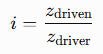
The corresponding speed relationship is the inverse. This basic relationship does not replace the geometric and strength calculations required to design the bevel gear pair.
10.6 What Materials Are Used to Manufacture Bevel Gears?
Carbon steels and alloy steels are common choices. Depending on loading and durability requirements, a gear may use through hardening or case hardening, including carburizing and quenching. Material and heat treatment should be specified according to the design loads, surface durability requirements, and manufacturing process.
10.7 Are Spiral Bevel Gears Stronger Than Straight Bevel Gears?
Not necessarily. Spiral bevel gears often provide smoother engagement, but load capacity depends on tooth geometry, dimensions, material, heat treatment, manufacturing accuracy, lubrication, and mounting conditions. A properly designed straight bevel gear can be more suitable than a spiral bevel gear for some applications.
10.8 What Standards Apply to Bevel Gear Accuracy?
ISO 17485 establishes an accuracy classification system for unassembled bevel and hypoid gears and gear pairs. Applicable AGMA standards address additional subjects, including gear geometry, load rating, and assembly. Engineers should select the relevant standards based on the design and contractual requirements.
10.9 How Do You Identify a Replacement Bevel Gear?
Start with the original drawing or manufacturer documentation. Verify the tooth count, tooth form, module reference, shaft angle, mounting dimensions, material, heat treatment, and mating gear geometry. If documentation is unavailable, perform a detailed dimensional and engineering assessment rather than relying on visual similarity.
10.10 How Do You Choose a Bevel Gear Manufacturer?
Evaluate the manufacturer’s design capability, experience with the required gear type, tooth-cutting and finishing processes, heat-treatment controls, inspection equipment, and material traceability. For critical industrial drives, also confirm that the manufacturer can verify the mating gear geometry and provide appropriate dimensional and quality documentation.
Conclusion
Bevel gears provide a practical solution for transmitting power between intersecting shafts, but reliable performance depends on matching the gear geometry to the operating conditions and installation requirements.
Engineers should consider tooth form, module, pitch geometry, torque, speed, material, heat treatment, lubrication, accuracy, and assembly as parts of one transmission design. Industrial applications also require careful identification of the actual gear type: large mining girth gears, sugar mill bull gears, paper machine drive gears, and crane slewing gears should not be confused with bevel gears simply because they operate in heavy-duty equipment.
For custom or replacement bevel gears, accurate technical information and verification of the complete mating arrangement are the foundations of dependable service life.