
A spur gear is one of the most widely used components in mechanical power transmission. Its straight teeth engage with those of another gear to transmit torque and rotary motion between parallel shafts. Because spur gears have a relatively simple geometry and are straightforward to manufacture and inspect, they are common in industrial gearboxes, reducers, machine drives, and heavy-duty equipment.
However, a spur gear is not automatically suitable for every application. Engineers must evaluate tooth geometry, module, transmitted load, rotational speed, material properties, lubrication, accuracy, and the stiffness of the complete transmission system.
This guide explains how spur gears work, how engineers calculate and specify their geometry, where they are used in industry, and what to consider when selecting, manufacturing, or replacing a spur gear.
1. What Is a Spur Gear?
A spur gear is a cylindrical gear with teeth that run parallel to its rotational axis. It typically transmits motion between parallel shafts through direct tooth engagement. Most conventional spur gears use involute tooth profiles, which support a consistent angular velocity ratio when correctly meshed.
Spur gears are used in everything from compact gearboxes to large industrial transmissions. Their straightforward tooth geometry can simplify manufacturing and inspection compared with some alternative gear arrangements.
Key terminology includes:
- Number of teeth (z): The total number of teeth on the gear.
- Module (m): A metric measure of tooth size. For a standard spur gear, module is the reference diameter divided by the number of teeth.
- Reference diameter (d): The diameter of the reference circle used to define the gear’s nominal geometry.
- Pressure angle (α): The angle that defines the direction of the tooth contact force relative to the tangent at the reference point.
- Face width (b): The axial width of the toothed region.
- Backlash: The clearance between mating teeth under a defined measurement condition.
The basic relationship between module, reference diameter, and tooth count is:
d=mz
For example, a spur gear with a module of 5mm and 40 teeth has a reference diameter of 200mm, assuming the standard module definition and geometry apply.
In an industrial gearbox, a smaller spur gear is often called a pinion, while the larger mating component is called the gear or wheel. The distinction describes the members of a gear pair, not a separate tooth geometry.
2. How Do Spur Gears Work?
Spur Gear Meshing and Motion Transmission
When two spur gears mesh, the teeth transmit force through contact along their working profiles. As the driving gear rotates, its teeth push the mating gear’s teeth, transferring motion and torque from one shaft to the other.
For standard external spur gears, the shafts rotate in opposite directions. Spur gears generate a tangential force that transmits torque and a radial separating force that loads the shafts and bearings. Unlike helical gears, ideal spur gears do not generate axial thrust from the tooth helix because their teeth are parallel to the axis.
Reliable operation depends on more than correct tooth profiles. Center distance, alignment, backlash, bearing condition, lubrication, and manufacturing accuracy all influence tooth contact and load distribution.
Spur Gear Ratio Calculation
For a simple external gear pair, the magnitude of the gear ratio is:
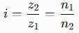
Where:
- z1 and z2 are the tooth counts of the driving and driven gears.
- n1 and n2 are their rotational speeds.
If a driving gear has 20 teeth and the driven gear has 60 teeth, the ratio magnitude is 3:1. The driven gear rotates at one-third of the driving gear’s speed, while its available torque increases in proportion to the ratio in an ideal lossless system.
Actual output torque is reduced by transmission losses. Gear design must also account for load fluctuations, starts and stops, and shock loading where these occur.
For standard, unmodified external spur gears with compatible tooth geometry, the nominal center distance is:
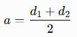
Profile shifts, nonstandard geometry, and other design modifications may change the applicable relationship. Engineers should use the specified gear geometry rather than relying on the basic formula alone.
3. Types of Spur Gears and Related Gear Arrangements
Standard Spur Gears and Pinions
Standard spur gears are used in gearboxes, reducers, industrial machines, and transmission stages where parallel shafts are required. A spur pinion may drive a larger gear to reduce output speed and increase available torque.
The design depends on the required ratio, tooth count, module, face width, material, and load capacity. A compact high-speed gearbox and a heavy-duty industrial drive may both use spur gears, but their material, accuracy, lubrication, and strength requirements can differ substantially.
Large, Heavy-Duty, and Open Spur Gears
Large spur gears can be used in custom machinery and heavy-duty drives when straight-tooth geometry is appropriate. Their design must account for transmitted torque, shaft deflection, alignment, manufacturing accuracy, and the operating environment.
It is important to distinguish a spur gear from a girth gear or ring gear. These terms describe different gear forms or arrangements, and they do not automatically specify straight teeth. Many large girth gears used in mining mills and cement kilns use tooth geometries selected for the particular drive.
When specifying large-module gears, engineers should define the tooth geometry, module, reference diameter, accuracy requirements, material, and mating component rather than using the general label “large gear” alone.
Spur Gears Compared with Other Gear Types
Spur and helical gears both commonly transmit power between parallel shafts, but their tooth geometry differs.
- Spur gears: Straight teeth, no helix-induced axial thrust, and relatively simple manufacturing and inspection.
- Helical gears: Angled teeth with more gradual engagement, but they generate axial thrust that the shaft and bearing arrangement must accommodate.
- Bevel gears: Used for transmissions between intersecting shafts.
- Worm gears: Use a worm and worm wheel arrangement, often for large ratios in a compact layout, with efficiency dependent on design and operating conditions.
- Planetary gear systems: Use sun, planet, and ring gears arranged around a shared axis; individual gear meshes may use spur or helical teeth.
The right arrangement depends on the required ratio, load, available space, operating speed, efficiency, noise, and maintenance requirements. When both parallel-shaft options remain open, a direct spur vs helical gears comparison usually settles the choice before tooth geometry is fixed.
4. Spur Gear Design: Key Engineering Parameters
Geometry and Tooth Dimensions
Spur gear design begins with compatible tooth geometry and the required transmission ratio. Engineers must define:
- Module and tooth count: Establish the basic tooth size and reference diameter.
- Pressure angle: Influences tooth geometry and the direction of forces transmitted to shafts and bearings.
- Addendum and dedendum: Define the tooth height above and below the reference circle.
- Face width: Affects load distribution across the tooth face, but wider teeth do not compensate for poor alignment or inadequate support.
- Backlash and center distance: Influence tooth clearance, operating behavior, and the risk of interference or excessive contact.
- Profile shift and tooth modifications: May be used to address specific geometry, strength, contact, or operating requirements.
For a standard external spur gear pair with the same module and compatible reference geometry, the nominal center distance is determined by the two reference diameters. If profile shifts or other modifications are present, the design must account for them explicitly.
Strength, Materials, and Heat Treatment
A spur gear must withstand tooth-root bending stress and tooth-flank contact stress over its intended service life. The engineering assessment should consider transmitted torque, speed, duty cycle, shock loads, starts and stops, lubrication, and the stiffness of the complete transmission.
Steel is widely used for industrial spur gears, but the appropriate material depends on the application. Material strength, toughness, hardenability, machinability, and heat-treatment response all affect suitability.
Common treatment approaches include:
- Through-hardening: Hardens the gear material through a substantial portion of its section, depending on material and process.
- Induction hardening: Locally hardens selected surfaces, often the tooth region, while retaining a tougher supporting material.
- Case hardening: Produces a hard surface layer with a supporting core designed to provide the required combination of wear resistance and toughness.
The choice should follow the load requirements, gear size, tooth geometry, manufacturing route, and specified material properties. A treatment that works well for one gear may not be appropriate for another.
Accuracy and Manufacturing Requirements
Gear accuracy affects tooth contact, noise, vibration, and load distribution. The required accuracy level should match the operating speed, service conditions, and design specification.
ISO 1328-1 addresses flank tolerance classification for cylindrical gears. The ISO 6336 series provides methods for calculating the load capacity of spur and helical gears, including tooth-root bending and surface durability. These standards serve different purposes: dimensional or flank accuracy classification does not, by itself, establish adequate load capacity.
Manufacturing may involve blank preparation, gear cutting, heat treatment, and finishing or grinding where required. Quality control should follow the drawing and contract requirements, with appropriate checks for tooth geometry, runout, material, hardness, and dimensional conformity.
5. Industrial Applications of Spur Gears
Mining and Cement Plants
Spur gears may be used in suitable mining machinery, reducers, crushers, auxiliary drives, and other industrial transmission stages. However, large ball mill and SAG mill girth gears are not necessarily spur gears; their geometry depends on the drive design.
Cement plants use many types of gears in rotary kiln drives, cement mills, vertical mills, and material-handling systems. Engineers should identify whether the component is a spur gear, helical gear, pinion, or girth gear before defining a replacement.
Sugar Mills and Cane Processing
Sugar production equipment can use spur gears in selected gearbox stages, cane mill drives, crushers, shredders, and auxiliary machinery. The exact arrangement depends on the equipment and its transmission design.
For sugar mill replacement gears, engineers should confirm the tooth geometry, module, shaft interfaces, material, and mating component. Terms such as bull gear, crown gear, and pinion can vary with equipment convention and should not substitute for a complete specification.
Rubber Machinery
Rubber mills, open mixing mills, internal mixers, Banbury mixers, calenders, extruders, and vulcanizing equipment may use spur gears in suitable transmission stages.
Rubber machinery drives can experience high torque, variable loads, and shock conditions. Gear selection should therefore consider tooth-root strength, surface durability, lubrication, alignment, and the operating cycle. A gearbox may use spur, helical, or other gear arrangements depending on its design.
Steel Plants and Rolling Mills
Steel plants use gears in rolling mill drives, pinion stands, coilers, recoilers, furnace mechanisms, and material-handling systems. Spur gears may be appropriate for certain parallel-shaft stages, but the complete equipment can include helical and specialized gear arrangements as well.
For steel mill replacement gears, assess the load spectrum, reversing duty where applicable, shaft and bearing support, lubrication, and the condition of the mating gear. Matching the nominal dimensions without verifying the original geometry can lead to poor meshing or premature failure.
Paper Mills
Paper machine drive systems may contain spur gears in selected transmission stages serving refiners, pulpers, calenders, rewinders, and dryer-cylinder drives. Not every paper machine gear is a spur gear; the arrangement depends on the machine’s drive architecture.
When planning paper machine gear replacement, verify the original gear type, tooth geometry, mounting dimensions, and operating requirements. For large or heavy-duty paper mill gears, also assess alignment, lubrication, and the condition of the mating components.
Marine and Heavy-Duty Equipment
Spur gears can be used in suitable marine gearboxes, winches, dredger drives, and shipyard equipment. This includes marine grab bucket gears for dredging and bulk-handling machinery. However, many marine reduction gears use helical or other tooth geometries, particularly where smooth operation and high power transmission are important.
Selection should account for torque, speed, duty cycle, lubrication, environmental exposure, and the requirements of the complete transmission. Replacement gears must match the original design and the mating component.
Power Generation and Wind Turbines
Spur gears may be found in auxiliary power equipment, industrial gearboxes, and selected power transmission stages. Wind turbines commonly use planetary and parallel-shaft gearbox stages, and the tooth geometry varies with the design.
A wind turbine’s yaw and pitch systems may use pinions engaging ring gears, but these components should not automatically be classified as spur gears. Engineers should identify the actual geometry and operating function before selecting or specifying replacement parts.
Port Cranes and Slewing Systems
Port cranes, container cranes, tower cranes, and mobile cranes use various gear arrangements in hoisting, luffing, trolley, and slewing systems. Spur gears may be used in suitable gearbox stages, while slewing drives may employ pinions engaging a slewing ring gear.
For crane gear replacement, verify the tooth geometry, mating gear, mounting arrangement, load conditions, and required accuracy. The terms slewing gear and slewing pinion describe a function or component role, not necessarily one particular tooth geometry.
6. Common Spur Gear Failure Modes and Prevention
Spur gear failures commonly involve tooth-root fatigue, surface fatigue, scuffing, abrasive wear, or tooth breakage. Misalignment, poor lubrication, contamination, and overload can contribute to these problems.
| Failure mode | Possible contributing factors | Inspection or prevention |
|---|---|---|
| Tooth-root fatigue | Repeated bending loads, overload, or stress concentration | Inspect tooth roots and review loading conditions |
| Pitting | Contact stress, lubrication problems, or unsuitable material properties | Inspect tooth flanks, lubricant condition, and load distribution |
| Scuffing | Lubrication breakdown or excessive frictional heating | Check lubricant supply, tooth surfaces, and operating conditions |
| Uneven wear | Misalignment, runout, poor contact, or incorrect backlash | Check alignment, backlash, and tooth contact pattern |
| Tooth breakage | Overload, impact, or accumulated fatigue damage | Investigate the failure mechanism and assess the complete drive |
Inspection should look beyond the damaged tooth. Engineers should check the mating gear, shaft and bearing condition, backlash, alignment, lubrication system, and operating history. For critical drives, documented inspection trends can help identify developing problems before they cause an unplanned shutdown.
7. How to Select the Right Spur Gear
A reliable selection process starts with operating requirements and ends with verification of the assembled transmission.
- Define the duty: Establish transmitted power, torque, rotational speed, ratio, load fluctuations, starts and stops, and required service life.
- Specify the geometry: Confirm module, tooth count, pressure angle, reference diameter, face width, backlash, center distance, and shaft arrangement.
- Evaluate strength: Check tooth-root bending and tooth-flank contact capacity using an appropriate design method and the required safety criteria.
- Select material and treatment: Consider strength, toughness, surface durability, manufacturing feasibility, and operating conditions.
- Confirm accuracy and compatibility: Define the required gear quality and dimensional tolerances, and verify the mating gear and mounting arrangement.
- Plan maintenance: Consider lubrication, inspection access, replacement lead time, and whether the mating gear should be inspected during replacement.
For large spur gears and heavy-duty industrial drives, the component must be evaluated as part of the system. A gear that matches the nominal dimensions but fails to meet the load, accuracy, or contact requirements is not a suitable replacement.
8. Spur Gear Manufacturing, Inspection, and Replacement
Manufacturing and Quality Control
Spur gear manufacturing may include blank preparation, machining, gear cutting, heat treatment, and finishing or grinding when specified. For OEM spur gear supply, drawings and material specifications are reproduced against the required tolerances and heat-treatment cycle, with inspection records to support traceability. The process depends on the gear’s size, material, geometry, accuracy requirements, and service conditions.
Quality control may include:
- Material grade verification and traceability.
- Tooth geometry and flank inspection.
- Runout and relevant dimensional checks.
- Hardness and heat-treatment verification.
- Documentation against the drawing and agreed acceptance criteria.
Inspection requirements should be defined before production. ISO or AGMA requirements should be applied according to the project’s specified scope rather than assumed to be interchangeable.
Spur Gear Replacement
Before ordering a replacement spur gear, collect the original drawing and identify the gear’s geometry and interfaces. If the drawing is unavailable, measurements should be taken carefully and verified against the mating gear where possible.
Key information includes:
- Tooth count, module, and pressure angle.
- Reference diameter and face width.
- Shaft bore, keyway, spline, or other mounting details.
- Material and heat treatment, where known.
- Required accuracy and operating conditions.
- Mating gear geometry and current condition.
Do not select a replacement using outside diameter alone. The gear’s tooth geometry, mounting dimensions, and compatibility with the mating gear must all be verified. If the original gear failed, determine whether overload, lubrication, misalignment, or another issue contributed before installing the replacement.
Choosing a Custom Industrial Gear Manufacturer
A qualified spur gear manufacturer should be able to interpret engineering drawings, produce the specified tooth geometry, control material and heat treatment, and verify the finished component against agreed requirements.
For large spur gears and replacement industrial gears, assess the supplier’s experience with comparable gear types and sizes, gear-cutting and finishing capability, inspection methods, material traceability, and technical support. A supplier’s ability to meet the actual application requirements is more important than nominal machining capability alone.
9. Frequently Asked Questions About Spur Gears
1. What is a spur gear used for?
A spur gear transmits rotary motion and torque between parallel shafts. It is used in gearboxes, reducers, industrial machinery, and other systems where straight-tooth gearing is appropriate.
2. How do you calculate a spur gear ratio?
For a simple external gear pair, divide the driven gear’s tooth count by the driving gear’s tooth count. The speed ratio is the inverse relationship between their rotational speeds, and the gears rotate in opposite directions.
3. What is the difference between spur gears and helical gears?
Spur gears have straight teeth parallel to the axis, while helical gears have angled teeth. Spur gears do not generate helix-induced axial thrust, whereas helical gears do. Helical gears generally engage more gradually, but the best choice depends on the load, speed, bearing arrangement, and application.
4. How do you calculate the module of a spur gear?
For a standard spur gear, module is the reference diameter divided by the number of teeth:

Module is expressed in millimetres in the metric system. For a replacement gear, ensure the reference diameter and tooth-count convention are correctly identified.
5. What materials are used for heavy-duty spur gears?
Steel is commonly used, with the grade and heat treatment selected according to load, toughness, wear resistance, and manufacturing requirements. Through-hardening, induction hardening, and case hardening may be suitable for different applications.
6. What causes spur gear tooth failure?
Common causes include bending fatigue, pitting, scuffing, overload, contamination, inadequate lubrication, and misalignment. Inspection should include the mating gear and supporting components to identify the root cause.
7. Can spur gears be used for high-torque applications?
Yes, when the gear geometry, material, face width, tooth strength, and complete transmission design are appropriate for the load. Suitability must be confirmed by engineering calculations and consideration of the actual operating conditions.
8. How do you measure a spur gear for replacement?
Record the tooth count, module, pressure angle, reference dimensions, face width, mounting interface, and mating gear details. Outside diameter alone is not sufficient to identify a compatible replacement.
9. Are large spur gears suitable for open industrial drives?
They can be suitable when straight-tooth geometry meets the drive’s requirements. However, many large mill and kiln drives use girth gears with geometry specific to the equipment, so the original design must be verified before specifying a replacement.
10. What should you look for in a custom spur gear manufacturer?
Look for relevant gear engineering experience, suitable gear-cutting and finishing capability, material and heat-treatment controls, inspection procedures, traceability, and the ability to meet the specified geometry and quality requirements.
A spur gear’s simple geometry makes it a versatile transmission component, but dependable performance still requires correct design, manufacturing, and installation. By evaluating tooth geometry, load capacity, materials, accuracy, lubrication, and mating gear compatibility together, engineers can select and maintain spur gears that meet the real demands of industrial machinery.