
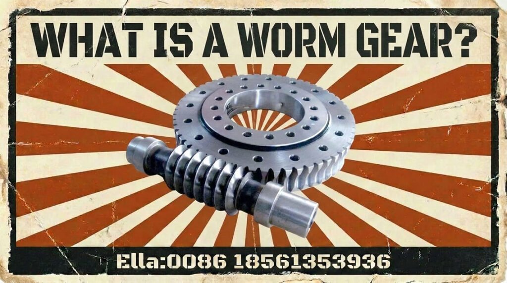
A worm gear is a mechanical transmission that uses a screw-like worm to drive a mating worm wheel, typically transferring motion between shafts arranged at right angles. It is widely used where compact packaging, substantial speed reduction, and controlled motion are important.
However, worm gearing also introduces engineering trade-offs. Sliding contact between the teeth affects efficiency, lubrication, wear, and heat generation. Selecting a suitable worm gear therefore requires more than matching a speed ratio or center distance: engineers must evaluate geometry, material compatibility, loading, operating temperature, and the intended duty cycle.
This guide explains how worm gears work, their principal types, key design parameters, material and manufacturing considerations, industrial applications, and practical replacement criteria.
1. What Is a Worm Gear?
A worm gear set consists of two principal components:
- Worm: A screw-like component with one or more helical threads, usually mounted on the input shaft.
- Worm wheel: A toothed wheel designed to mesh with the worm and transmit torque to the output shaft.
The shafts are commonly arranged at 90° and are generally non-intersecting. As the worm rotates, its thread surfaces slide against the wheel teeth, causing the wheel to rotate at a lower speed.
Worm drives are particularly useful when machinery requires a substantial speed reduction within a compact arrangement. Depending on their geometry and friction conditions, they can also provide resistance to back-driving. However, this behavior must be verified for the actual operating conditions rather than assumed.
Worm gears are distinct from conventional spur gears, helical gears, and large industrial open gears. For example, a mining mill’s girth gear or a cement kiln’s large ring gear typically belongs to a different transmission arrangement, even though both systems reduce speed and transmit high torque.
2. How Does a Worm Gear Work?
The operating principle
The worm behaves like a rotating screw engaging with the teeth of the worm wheel. Each revolution of the worm advances the wheel according to the worm’s number of starts and the wheel’s tooth count.
For a simple worm gear set, the nominal speed reduction ratio is:

Where:
- i= transmission ratio
- z2 = number of teeth on the worm wheel
- z1 = number of starts on the worm
For example, a single-start worm driving a 40-tooth wheel gives a nominal ratio of 40:1. The wheel turns once for every 40 revolutions of the worm, assuming the intended operating arrangement.
A multi-start worm advances the wheel farther per revolution and can improve efficiency in suitable designs, although the resulting ratio and other performance characteristics must be evaluated together.
Sliding contact, friction, and heat
Unlike many conventional spur gear pairs, which primarily transmit motion through rolling and sliding contact, worm gearing involves substantial sliding along the tooth surfaces. This sliding creates frictional losses and heat.
Three factors are especially important:
- Lead angle: Affects the relationship between sliding, load transmission, and efficiency.
- Lubrication: Controls friction, wear, and the formation of a protective lubricant film.
- Operating conditions: Input speed, transmitted torque, duty cycle, and cooling capacity influence the thermal balance.
Back-driving and self-locking
Some worm gear sets resist being driven backward from the wheel side. This can be useful in certain positioning and adjustment mechanisms, but a worm gear is not automatically self-locking.
Back-driving behavior depends on the geometry, friction coefficient, lubrication, temperature, wear, vibration, and external loading. Where a suspended load or personnel safety is involved, use a properly rated brake or other independent holding mechanism rather than relying solely on worm gearing.
3. Types of Worm Gears and Worm Gear Drives
Worm gear designs differ in thread geometry, contact pattern, and manufacturing method. These differences influence load capacity, efficiency, lubrication requirements, and manufacturing complexity.
Cylindrical worm gears
Cylindrical worm drives use a worm with a generally cylindrical body and a mating wheel whose teeth conform to the required mesh geometry. They are common in industrial speed reducers because their design and manufacturing methods are well established.
ISO 10828:2024 addresses the geometry of several common worm profiles, designated A, C, I, K, and N. The correct profile and its corresponding wheel geometry must be selected as a compatible system.
Single-start and multi-start worms
- Single-start worm: One helical thread; suitable for designs requiring a relatively high reduction ratio.
- Multi-start worm: Two or more thread starts; generally provides a higher wheel advance per worm revolution and can support improved efficiency in an appropriately designed set.
The number of starts alone does not determine performance. Lead angle, tooth geometry, material pairing, lubrication, and load conditions also matter.
Enveloping worm gears
Enveloping designs increase the extent of contact between the worm and wheel compared with conventional non-enveloping arrangements. Depending on the configuration, this can support higher load capacity, but it also increases geometric and manufacturing complexity.
How worm gears differ from other industrial gears
A worm wheel is not interchangeable with a spur gear, helical gear, bevel gear, or planetary gear simply because the components share a transmission function.
For example:
- Spur and helical gears are commonly used for parallel-shaft transmissions.
- Bevel gears transmit motion between intersecting shafts in typical arrangements.
- Planetary gears distribute load among multiple planet gears within a compact coaxial system.
- Girth gears and large ring gears are used in many large rotary machines, including ball mills and rotary kilns.
- Worm gears are most appropriate when their particular combination of reduction ratio, shaft arrangement, packaging, and operating characteristics fits the application.
Choosing the gear architecture should precede detailed sizing and procurement.
4. Key Worm Gear Design Parameters
Correct worm gear design requires the geometry, load, thermal conditions, and installation arrangement to be evaluated together.
Geometry and compatibility
Important parameters include:
- Module: A metric parameter describing tooth size. Worm gear geometry involves direction-specific module definitions, so the relevant module and reference system must be identified.
- Number of starts and wheel teeth: These determine the nominal transmission ratio.
- Lead and lead angle: Describe the axial advance of the worm thread and strongly influence sliding behavior.
- Reference or pitch diameters: Used to define the geometry and operating relationships of the components.
- Center distance: The distance between shaft axes; it must match the designed mesh geometry.
- Pressure angle and tooth profile: Affect the contact geometry and force transmission.
- Backlash: The clearance between mating tooth flanks, which must suit the application, lubrication, and temperature range.
Worm and wheel teeth must be geometrically compatible. Matching only the nominal module and outside dimensions is not enough to guarantee correct contact.
Load, speed, and thermal capacity
Engineers should establish the transmitted torque, input speed, operating duration, starts and stops, shock loads, and expected service life. The design must also account for shaft deflection, bearing support, housing stiffness, and alignment.
Unlike a gear pair whose rating is governed primarily by tooth-root strength and surface fatigue, a worm drive may be limited by several interacting factors:
- Tooth-surface wear or pitting
- Tooth-root strength
- Worm or wheel deflection
- Scuffing and lubrication failure
- Heat generation and heat rejection
A drive can have adequate mechanical strength yet still fail in service if its thermal capacity is insufficient for continuous operation.
Quality grades and standards
ISO and AGMA documents may be specified for appropriate aspects of gear geometry, rating, and manufacturing quality. Their applicability depends on the gear type and the agreed design basis. For worm gear profile geometry, ISO 10828:2024 is a relevant reference; the selected load-rating method must also be suitable for the actual configuration.
A manufacturing accuracy grade is not the same as a load-capacity rating. A highly accurate gear can still be undersized for the transmitted torque, and a strong gear can perform poorly if alignment, backlash, or contact geometry is incorrect.
5. Worm Gear Materials, Manufacturing, and Quality Control
Material selection
A common material combination is a hardened steel worm paired with a bronze-alloy worm wheel. The steel worm provides a wear-resistant working surface, while a suitable bronze alloy can provide favorable sliding and wear behavior against the worm.
This is not a universal specification. Material selection depends on transmitted load, sliding velocity, lubrication, operating temperature, shock loading, manufacturing method, and the required service life. Other materials may be appropriate in lightly loaded or specialized applications.
Manufacturing and heat treatment
The worm thread may be produced by turning, milling, grinding, or other suitable processes. The worm wheel is manufactured using a process and tooling compatible with the intended tooth geometry. Finishing and heat treatment must be controlled so the finished components meet the required dimensional, surface, and mechanical properties.
Case hardening may be specified for a steel worm when required by the design. It should not be treated as a mandatory process for every worm gear set; the material, hardening method, and finished condition must follow the approved design.
Inspection and quality control
A practical inspection plan may include:
- Verification of material certificates and heat-treatment records
- Dimensional checks of reference diameters, center-distance requirements, and mounting interfaces
- Inspection of thread or tooth geometry and surface condition
- Verification of backlash and tooth-contact pattern during assembly
- Checks of bearing condition, alignment, lubrication, and operating temperature during commissioning
For replacement work, supplying the worm and worm wheel as a matched set is often preferable, particularly when the original profile or manufacturing details are not fully documented.
6. Industrial Applications of Worm Gears
Worm drives are used across many industries, but they are generally suited to particular mechanisms rather than every major transmission in a plant. The following examples distinguish appropriate potential uses from large industrial gear systems that typically use other architectures.
6.1 Lifting Equipment, Cranes, and Port Machinery
Worm gear drives can be used in selected positioning mechanisms, auxiliary drives, and compact reduction units. Their suitability depends on load, duty cycle, efficiency, and thermal requirements.
Port cranes, container cranes, and other industrial cranes also use spur, helical, planetary, and slewing ring gear-and-pinion arrangements. A crane slewing ring gear, for example, should not be classified as a worm wheel unless the actual design uses worm gearing.
For lifting applications, holding performance and braking must be evaluated as part of the complete safety system. Self-locking behavior alone is not an adequate substitute for a properly engineered brake.
6.2 Marine Equipment and Shipboard Machinery
Selected marine winches, actuators, and auxiliary mechanisms may use worm gearing where compact reduction or controlled movement is useful. Engineers must account for corrosion protection, shock loading, lubrication reliability, and maintenance access.
Large marine main drive gears and ship main reduction gears are a separate engineering category. High-power propulsion systems generally require a transmission architecture designed around their specific torque, speed, efficiency, and reliability requirements; a worm drive should not be presumed suitable.
6.3 Wind Turbine Pitch and Yaw Systems
Wind turbines use gear mechanisms in their pitch and yaw systems to control blade angle and nacelle orientation. Depending on the design, a system may contain electric or hydraulic actuation, reduction gearing, and a ring gear engaged by one or more pinions.
A wind turbine yaw ring gear, yaw pinion, or planetary gearbox gear is not automatically a worm gear. When specifying wind turbine gear replacement, identify the actual transmission arrangement and component geometry before selecting a replacement.
6.4 Steel Plants and Metallurgical Equipment
Worm drives may suit selected auxiliary positioning or adjustment mechanisms where compact reduction is advantageous. Operating conditions in steel plants can include high ambient temperatures, contamination, shock loads, and demanding duty cycles, all of which affect material and lubrication choices.
By contrast, rolling mill main drives, converter tilting systems, caster drives, and heavy slab-handling equipment may use large spur, helical, bevel, or specialized gear systems. These should be engineered according to their actual mechanical arrangement rather than grouped indiscriminately under worm gearing.
6.5 Mining and Cement Equipment
Selected auxiliary mechanisms, feeders, and positioning devices may use worm gear reducers. However, the major drives of ball mills, SAG mills, rotary kilns, and cement mills often use different configurations because of their high power and continuous-duty requirements.
Large ball mill gears, SAG mill girth gears, cement kiln girth gears, and rotary kiln gears are commonly large open gear arrangements. Their design and replacement requirements differ significantly from those of an enclosed worm gearbox. When specifying a mining or cement gear, confirm whether the required component is a worm wheel, pinion, girth gear, or another gear type.
6.6 Sugar Mills and Cane Processing
Worm drives may be suitable for selected auxiliary drives, adjustment mechanisms, or handling equipment, depending on the machine layout and required torque.
Main sugar mill drives often involve heavy-duty bull gears, pinions, and open gearing designed for high torque and harsh operating conditions. A cane mill bull gear or sugar mill pinion should therefore be treated as a distinct component, not assumed to be part of a worm gear set.
6.7 Rubber Machinery
Worm gearing may be used in selected auxiliary adjustment, positioning, or feed mechanisms. Its suitability depends on load, speed, temperature, and whether the drive operates intermittently or continuously. Tire curing presses are one case where this fits: precision M6 worm gear sets drive the mold opening and closing mechanism, where a tin-bronze wheel running against a hardened 40Cr worm keeps friction low and holds mold position through repeated clamp and unclamp cycles.
The main drives of rubber mixing mills, Banbury internal mixers, rubber calenders, and extruders can require high torque and sustained operation. These machines may use other gear arrangements, so the terms rubber mill drive gears, internal mixer gears, and rubber extruder gears should not be treated as synonyms for worm gears.
6.8 Paper Mills and Paper Machines
Selected paper-machine auxiliary drives or adjustment mechanisms may use worm gear reducers where compact reduction is beneficial. Designers should consider the required positioning accuracy, lubrication, maintenance access, and operating environment.
Paper machine drive gears, dryer cylinder drive gears, Yankee dryer gears, and other production-line transmissions may use different gear configurations to maintain synchronization and withstand continuous operation. When planning paper machine gear replacement, identify the actual gear type, geometry, and duty requirements.
6.9 Power Generation and General Industrial Machinery
Worm gear reducers can be found in selected conveyors, valves, actuators, and auxiliary mechanisms across power generation and general manufacturing. Their value depends on whether the application benefits from their packaging and reduction characteristics.
For continuous-duty or energy-intensive applications, compare worm drives with helical or planetary reducers. The decision should include efficiency, heat rejection, lubrication, noise, serviceability, and the cost of energy over the expected operating life.
7. Worm Gear Advantages and Limitations
Worm gearing offers a useful combination of compactness and speed reduction, but its suitability depends on the operating requirements.
Advantages
- High reduction in a compact arrangement: A substantial reduction ratio can be achieved within one gear stage.
- Right-angle shaft arrangement: Useful where the input and output shafts must be arranged at an angle.
- Smooth operation: Properly designed and lubricated worm drives can operate with relatively low noise.
- Flexible motion control: Suitable for selected positioning, adjustment, and auxiliary drive applications.
Limitations
- Sliding friction: Can produce greater power losses than suitable rolling-dominant gear arrangements.
- Heat generation: Continuous operation may require careful thermal design and additional cooling.
- Lubrication sensitivity: Incorrect lubricant selection or inadequate oil supply can accelerate wear and cause surface damage.
- Potential wear limitations: Contact stress, sliding velocity, material pairing, and contamination affect service life.
- Self-locking uncertainty: Back-driving resistance varies with the design and operating conditions and should not be relied on as the sole safety measure.
The correct comparison is not simply worm gear versus spur gear. It is a comparison of complete transmission solutions under the same load, speed, duty cycle, space, efficiency, and maintenance requirements.
8. Common Worm Gear Failure Modes and Troubleshooting
Worm gear failures often involve a combination of sliding friction, lubrication problems, overload, and alignment errors. The appearance of the damage can help identify the likely cause, but inspection should include the entire transmission rather than the damaged tooth surface alone.
| Failure mode | Possible causes | Inspection or corrective action |
|---|---|---|
| Scuffing or scoring | Lubrication breakdown, excessive temperature, unsuitable material pairing | Check lubricant condition, oil supply, contact pattern, and temperature |
| Abrasive wear | Contamination, poor sealing, inadequate filtration | Inspect lubricant and seals; identify contamination sources |
| Pitting or surface fatigue | Excessive contact stress, poor alignment, inadequate lubrication | Review load, tooth contact, geometry, and lubrication |
| Tooth-root cracking or fracture | Overload, shock loading, fatigue, or material defects | Review load history and inspect material and heat-treatment records |
| Overheating | High sliding losses, excessive load, insufficient lubrication or cooling | Check duty cycle, lubricant level, cooling, and operating conditions |
| Excessive backlash or noise | Wear, bearing deterioration, misalignment, or incorrect assembly | Measure backlash and inspect bearings, mounting, and tooth contact |
A practical troubleshooting sequence
- Record the operating speed, load, temperature, noise, and lubrication condition.
- Inspect the worm, wheel, bearings, housing, and seals for visible damage or abnormal wear.
- Verify alignment, backlash, and the contact pattern against the design requirements.
- Check whether the actual duty cycle and transmitted load exceed the original design assumptions.
- Correct the root cause before installing replacement components, then verify performance during commissioning.
Replacing a worn wheel without investigating the worm, bearings, lubricant, and alignment can result in premature failure of the new components.
9. How to Select or Replace a Worm Gear Set
Selection should begin with the operating requirements and actual gear geometry, not just the required ratio.
Information needed for selection
Provide the manufacturer or gear designer with:
- Required transmission ratio and output speed
- Input power, speed, and transmitted torque
- Operating hours, load variation, and shock-loading conditions
- Shaft orientation, center distance, mounting interfaces, and available space
- Required backlash, positioning accuracy, and service life
- Lubrication method, ambient temperature, and thermal constraints
- Existing drawings, gear specifications, photographs, or physical samples
Replacing an existing worm gear
When replacing a worm gear set, verify the thread profile, lead, number of starts, wheel tooth count, reference dimensions, center distance, and material requirements. External dimensions alone cannot establish compatibility.
If the original drawings are unavailable, a qualified manufacturer may need to inspect the components and reconstruct the geometry. The replacement should be checked for mesh compatibility and load capacity, not simply manufactured to match the visible shape.
For custom industrial gear procurement, it is also important to clarify whether the requirement is for a complete worm and wheel set, a worm shaft, a wheel only, or a complete worm gearbox. These are different supply scopes.
10. Worm Gear Manufacturing Standards and Inspection
Engineering standards help establish consistent terminology, geometry, and design evaluation, but the selected standard must apply to the specific gear configuration.
ISO 10828:2024 covers common worm profiles and worm gear mesh geometry, including calculations related to the path of contact, conjugate wheel profile, and sliding velocities.
For a complete design or replacement project, the manufacturer and purchaser should agree on:
- The applicable geometry and load-rating method
- Required material grades and heat-treatment condition
- Dimensional and manufacturing tolerances
- Backlash and tooth-contact acceptance criteria
- Inspection documentation and traceability
- Lubrication and commissioning requirements
AGMA or other industry standards may be relevant where applicable, but an accuracy grade should never be interpreted as proof that a gear can carry the required load. Load rating, manufacturing accuracy, and material properties are separate considerations.
For custom or replacement worm gears, supplying the original drawings and operating data gives an industrial gear manufacturer a stronger basis for evaluating compatibility and performance.
11. Frequently Asked Questions About Worm Gears
1. What is a worm gear, and how does it work?
A worm gear is a transmission consisting of a screw-like worm and a mating toothed wheel. Rotation of the worm drives the wheel at a reduced speed, commonly between shafts arranged at right angles.
2. What is the difference between a worm and a worm wheel?
The worm is the threaded driving component, while the worm wheel is the toothed driven component. Their geometry must be designed to mesh correctly as a pair.
3. How do you calculate a worm gear ratio?
For a simple worm gear set, the nominal ratio is the number of teeth on the worm wheel divided by the number of starts on the worm:
For example, a 40-tooth wheel driven by a single-start worm gives a nominal 40:1 ratio.
4. Are worm gears self-locking?
Not necessarily. Self-locking depends on factors such as lead angle, friction, lubrication, and operating conditions. Applications involving suspended loads or safety-critical holding require an appropriately engineered braking system.
5. How efficient is a worm gear drive?
Efficiency varies with geometry, lead angle, surface finish, materials, speed, load, and lubrication. Sliding friction can produce significant losses, so efficiency should be evaluated for the actual operating conditions rather than assigned a universal value.
6. Which materials are commonly used for worm gears?
A common combination is a hardened steel worm and a bronze-alloy wheel. Other materials may be suitable depending on load, sliding conditions, lubrication, temperature, and application requirements.
7. What causes worm gears to overheat or wear prematurely?
Common causes include inadequate lubrication, unsuitable lubricant, excessive load, poor alignment, contamination, and insufficient heat dissipation. Correcting the root cause is essential before replacing damaged components.
8. When should you choose a worm gear instead of a helical or planetary gearbox?
Consider worm gearing when its compact layout, shaft arrangement, and reduction characteristics suit the application. Helical or planetary reducers may be preferable when efficiency, continuous high-power operation, or thermal performance is a priority.
9. Can a worm gear set be custom-manufactured or replaced using an existing sample?
Yes, provided the manufacturer can establish the required geometry, materials, tolerances, and operating conditions. A physical sample can help reconstruct the design, but a dimensional inspection and engineering assessment are still necessary.
10. What information is needed to order a replacement worm gear or worm wheel?
Provide drawings or samples, gear ratio, number of worm starts, wheel tooth count, geometry and mounting dimensions, material requirements, input speed, transmitted torque, and duty-cycle information. If the original specifications are unknown, arrange a technical review before manufacturing.
Conclusion
Worm gears provide a practical transmission solution when compact packaging, substantial speed reduction, and a particular shaft arrangement are important. Their performance, however, depends on compatible geometry, appropriate material pairing, effective lubrication, accurate alignment, and adequate thermal capacity.
For engineers selecting or replacing a worm gear set, the key is to evaluate the complete operating system rather than the gear dimensions alone. And for large industrial applications—including mining, cement, sugar, rubber, steel, marine, wind, paper, and port machinery—confirm the actual transmission architecture before specifying a replacement. A worm gear, a large spur gear, a girth gear, and a slewing ring gear serve different mechanical roles and require different design and manufacturing approaches.