
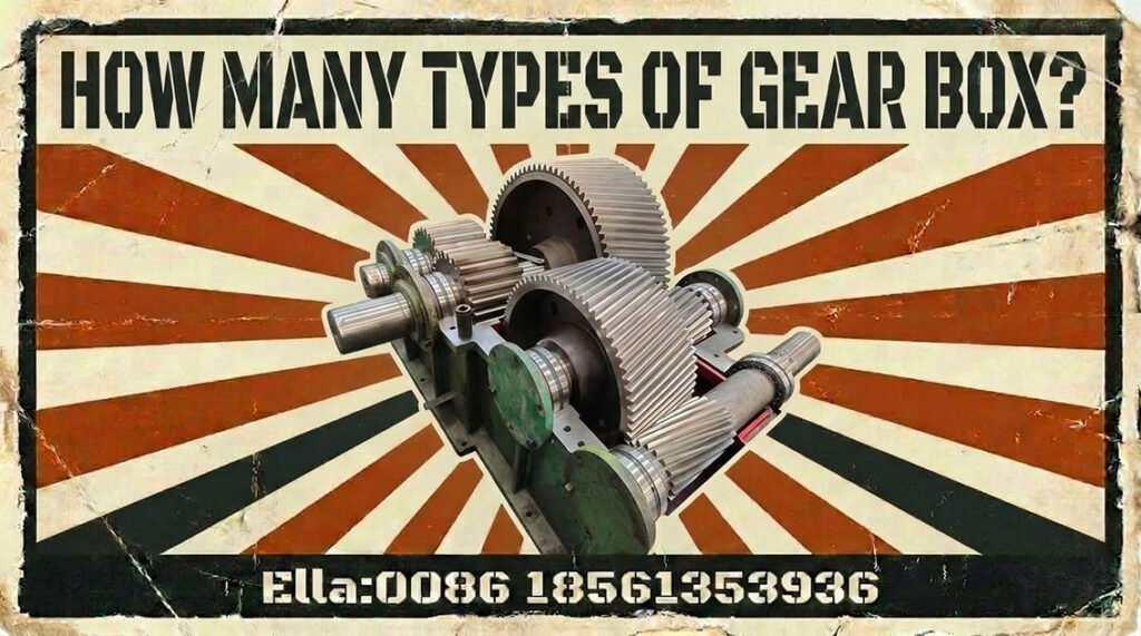
How Many Types of Gear Box? A Comprehensive Guide to Industrial Speed Reducers
Industrial gearboxes are not defined by a single design or operating principle. They combine different gear geometries, shaft arrangements, reduction ratios, materials, heat treatments, and lubrication systems to meet the requirements of specific machinery.
So, how many types of gearboxes are there? There is no single universally correct number. Gearboxes can be classified by gear type, shaft arrangement, transmission configuration, application, or duty. The most common industrial designs include spur, helical, bevel, worm, planetary, parallel-shaft, and helical-bevel gearboxes.
For engineers, gearbox selection should begin with the operating requirements rather than the gearbox name. Power, speed, output torque, duty cycle, load characteristics, service factor, mounting arrangement, environment, and required service life all influence the correct design.
What Is a Gearbox and How Does It Work?
A gearbox, also called a gear reducer or speed reducer, transmits mechanical power between shafts while changing rotational speed and torque.
In a typical reduction gearbox, the input shaft rotates at a higher speed than the output shaft. The gear ratio reduces output speed while increasing available output torque, subject to transmission efficiency and losses.
Important parameters when specifying an industrial gearbox include:
- Input power and speed
- Output speed and torque
- Reduction ratio
- Duty cycle and load characteristics
- Service or application factor
- Shaft arrangement
- Gear geometry and module
- Pitch diameter and face width
- Material and heat treatment
- Gear accuracy/quality
- Lubrication and operating temperature
Gear load capacity should be evaluated using an appropriate calculation method rather than relying only on nominal motor power. For cylindrical spur and helical gears, the ISO 6336 series provides calculation methods covering factors such as surface durability, tooth-root strength, materials, and variable loading.
How Many Types of Gearboxes Are There?
There is no meaningful universal count because several classification systems overlap. A helical gearbox, for example, can also be a coaxial gearbox, while a planetary gearbox can be combined with other stages.
The principal industrial gearbox families are:
Spur Gearboxes
Spur gears have straight teeth parallel to the gear axis. Their geometry is relatively simple, which can make them straightforward to manufacture and inspect.
They are suitable for applications where parallel shafts and relatively straightforward transmission arrangements are required. However, tooth engagement is less gradual than with helical gears, which can result in greater impact and noise at higher speeds.
Helical Gearboxes
Helical gears have teeth inclined relative to the gear axis. The gradual engagement of the teeth generally provides smoother transmission and higher load-carrying capability than an equivalent straight-tooth arrangement.
Helical gearboxes are widely used in industrial conveyors, mixers, pumps, compressors, process machinery, and other continuous-duty applications.
The helix angle also introduces axial forces, so bearing arrangement and shaft design must be considered together with the gear design.
Bevel Gearboxes
Bevel gears transmit power between intersecting shafts and are commonly used when a right-angle drive is required.
Straight bevel and spiral bevel gears have different tooth geometries and operating characteristics. Spiral bevel gears generally provide smoother engagement and are widely used where higher performance and smoother transmission are required.
Worm Gearboxes
A worm gearbox uses a worm and worm wheel to obtain substantial speed reduction within a compact arrangement.
The main engineering considerations include efficiency, sliding velocity, heat generation, lubrication, and the specific worm/wheel material combination. Worm drives should therefore not be selected solely because they provide a convenient reduction ratio.
Planetary Gearboxes
A planetary gearbox contains a sun gear, planet gears, and a ring gear. Multiple gears share the transmitted load, allowing a compact design with high torque density.
Planetary arrangements are particularly useful where space, torque density, coaxial output, or multiple-stage reduction are important. Their design and manufacturing requirements can be more demanding because load sharing, alignment, bearing loads, and gear accuracy all affect performance.
Parallel-Shaft and Helical-Bevel Gearboxes
Parallel-shaft gearboxes use gear stages arranged to maintain parallel input and output shafts. They are common where the machine layout requires a compact drive with substantial torque transmission.
Helical-bevel gearboxes combine helical and bevel gearing to provide right-angle transmission with the advantages of helical tooth engagement. These arrangements are frequently encountered in conveyors, material-handling systems, and heavy industrial machinery.
Gearbox Types by Shaft Arrangement
Gearboxes can also be classified according to the relationship between their input and output shafts.
Common arrangements include:
- Coaxial: input and output shafts share the same axis.
- Parallel-shaft: shafts are parallel but offset.
- Right-angle: power is transmitted through an approximately 90-degree shaft arrangement.
- Offset/right-angle configurations: used where machine layout requires both angular and positional flexibility.
Shaft arrangement affects installation space, bearing loading, coupling design, lubrication, and the way the gearbox interfaces with the driven machine.
For this reason, specifying only “a 20:1 gearbox,” for example, is not sufficient for engineering selection. The actual output torque, duty cycle, mounting position, shaft orientation, and load characteristics must also be defined.
Industrial Gearbox Types by Application
Different industries impose very different demands on industrial speed reducers. A gearbox for a paper machine is not necessarily suitable for a mining conveyor simply because their nominal power ratings are similar.
Sugar Mill Gearboxes
Sugar processing equipment can involve high torque, continuous operation, fluctuating loads, and demanding environmental conditions.
Gearboxes may be used in cane preparation, milling, conveying, and other process equipment. Design priorities include load capacity, shaft alignment, lubrication, thermal management, and resistance to repeated load variations.
Rubber Machinery Gearboxes
Rubber machinery places demanding loads on transmission systems. Rubber mixers, mills, extruders, and calenders can generate high torque requirements and cyclic or shock loading.
Gearbox design therefore needs to consider torque peaks, shaft stiffness, gear tooth strength, bearing loads, lubrication, and thermal performance rather than simply selecting a reducer according to motor rating.
Mining Gearboxes
Mining equipment subjects gearboxes to severe operating environments, including heavy loads, shock loading, dust, vibration, and contamination risks.
Typical applications include conveyors, crushers, mills, and material-handling systems. Reliability depends on correct load calculation, robust housing and shaft design, effective sealing, lubrication management, and appropriate gear and bearing capacity.
Cement Plant Gearboxes
Cement plants contain many high-load continuous-duty machines, including crushers, conveyors, mills, and kiln-related equipment.
Gearbox selection must account for transmitted torque, starting conditions, load variation, thermal behavior, lubrication, and alignment. For critical drives, maintenance access and condition monitoring can be as important as the initial gearbox rating.
Steel Plant Gearboxes
Steel production presents a combination of high loads, shock loading, temperature variation, and continuous operation.
Gearboxes may be used in conveyors, rolling equipment, cooling systems, and other production machinery. Tooth-root strength, surface durability, shaft stiffness, bearing capacity, and alignment are particularly important for heavily loaded drives.
Marine Gearboxes
Marine applications require high reliability under changing loads and environmental conditions. Gearbox design can involve strict requirements for lubrication, corrosion protection, vibration, noise, shaft alignment, and compact installation.
Marine gear calculations and industrial gear calculations should not automatically be treated as interchangeable. Application-specific requirements and the relevant standards need to be considered.
Power Generation Gearboxes
Gearboxes in power-generation facilities can serve generators, auxiliary systems, cooling equipment, pumps, fans, and other machinery.
Continuous operation places strong emphasis on reliability, lubrication, vibration control, thermal stability, and maintainability. For critical equipment, gearbox condition monitoring can help identify developing problems before catastrophic failure.
Wind Turbine Gearboxes
Wind turbine gearboxes increase the rotational speed from the turbine rotor to the generator. Their operating conditions are particularly demanding because the transmitted load varies with wind conditions and turbine operation.
Planetary and helical stages are commonly used in wind turbine drivetrain designs. Gear fatigue, bearing loads, lubrication, alignment, dynamic behavior, and load variation must all be considered.
Wind gearbox requirements are sufficiently specialized that turbine-specific design and reliability requirements should be evaluated rather than applying a generic industrial reducer specification. Current international standards also include dedicated requirements for wind turbine gearboxes.
Paper Mill Gearboxes
Paper machines demand stable, precise, and continuous power transmission. Gearboxes may drive rollers, conveyors, pulpers, refiners, and other process equipment.
Smooth operation, alignment, vibration, thermal stability, lubrication, and gear accuracy are important because unexpected gearbox downtime can interrupt an entire production process.
Port Crane Gearboxes
Port cranes use gearboxes for functions including hoisting, travelling, and slewing.
These drives can experience frequent starts and stops, load reversals, braking events, and dynamic loading. Gearbox selection therefore needs to consider the actual duty cycle and transient loads rather than only the rated motor power.
Gearbox Materials and Manufacturing Considerations
Gear and shaft materials must be selected according to transmitted load, required fatigue strength, manufacturing process, heat treatment, operating environment, and expected service life.
Alloy steels are widely used for industrial gearing. Where high surface durability is required, gears may use case hardening, such as carburizing followed by appropriate hardening and tempering processes. This can provide a hard tooth surface while retaining a tougher core.
Material selection is only one part of gear performance. Manufacturing quality, heat-treatment control, tooth geometry, residual stresses, surface finish, and inspection all influence the final load-carrying capability.
ISO 6336-5 specifically addresses material strength and quality and the influence of material and heat treatment on gear load-capacity calculations.
Gearbox Gear Quality, Design, and Manufacturing Standards
A professional gearbox specification should define measurable engineering requirements rather than relying on terms such as “high precision” or “heavy duty.”
Important parameters include:
- Module and pitch diameter
- Normal or transverse pressure angle, as applicable
- Helix angle
- Face width
- Tooth profile and lead
- Backlash
- Gear accuracy/quality grade
- Material and heat treatment
- Surface hardness
- Tooth-root and contact stress
- Lubrication requirements
For cylindrical spur and helical gears, ISO 6336 provides established calculation procedures for load capacity, including pitting resistance and tooth bending strength. The applicable scope and assumptions of the calculation method must be respected; a standard calculation is not a substitute for evaluating the complete assembled gearbox.
AGMA standards and rating practices are also widely used in industry. The correct approach is to specify the governing standard and calculation method for the particular gearbox rather than mixing terminology or quality grades from different systems without equivalence verification.
Common Industrial Gearbox Failure Modes
Industrial gearbox failures are usually caused by a combination of design, manufacturing, installation, lubrication, loading, and maintenance factors.
Common failure mechanisms include:
- Pitting: repeated contact stress causes fatigue damage on gear flanks.
- Scuffing: excessive sliding and inadequate lubrication can cause severe surface damage.
- Tooth breakage: overload, fatigue, stress concentration, or manufacturing defects can lead to tooth-root failure.
- Wear: abrasive particles, inadequate lubrication, or unsuitable operating conditions can progressively remove material.
- Bearing failure: excessive loads, misalignment, contamination, or lubrication problems can damage bearings.
- Overheating: excessive load, lubricant problems, insufficient cooling, or internal losses can raise operating temperature.
ISO 6336 includes calculation procedures addressing several gear failure mechanisms, including pitting, tooth-root breakage, flank fracture, scuffing, and micropitting.
Quick-Reference Table: Gearbox Failure Modes and Typical Causes
| Failure mode | Typical engineering causes | Key prevention focus |
|---|---|---|
| Tooth pitting | Repeated contact stress, unsuitable load conditions, lubrication issues | Gear rating, material, heat treatment, lubrication |
| Scuffing | High sliding, temperature, inadequate lubricant film | Lubrication and thermal control |
| Tooth breakage | Overload, fatigue, stress concentration | Tooth-root design and load calculation |
| Gear wear | Contamination, poor lubrication, abrasive particles | Sealing, filtration, lubricant management |
| Bearing failure | Misalignment, overload, contamination, lubrication problems | Bearing selection and shaft alignment |
| Overheating | Excessive load, lubricant problems, inadequate cooling | Thermal design and operating control |
How to Choose the Right Industrial Gearbox
Gearbox selection should follow the actual operating requirements of the driven machine.
A practical engineering sequence is:
- Determine input power and speed.
- Determine required output speed.
- Calculate the required output torque.
- Establish the reduction ratio.
- Identify the duty cycle and load characteristics.
- Account for the appropriate service/application factors.
- Select the shaft arrangement and mounting configuration.
- Evaluate gear, shaft, bearing, and housing capacity.
- Specify materials, heat treatment, gear quality, and lubrication.
- Verify thermal capacity, noise/vibration requirements, and maintenance conditions.
The critical point is that gearbox selection should be based on the actual driven load, including starting, stopping, shock, cyclic, or variable loads where applicable.
For heavily loaded applications, gear rating should distinguish between tooth-root bending strength and flank/contact fatigue. These are different failure mechanisms and should not be reduced to a single “gearbox capacity” figure.
Gearbox vs. Speed Reducer: Is There a Difference?
In industrial practice, gearbox, gear reducer, and speed reducer are frequently used interchangeably.
A speed reducer emphasizes the function of reducing rotational speed. Gearbox is a broader mechanical term describing the complete enclosed transmission assembly, which may contain one or multiple gear stages and associated shafts, bearings, lubrication, seals, and housing components.
The terminology itself is less important than clearly defining the engineering requirements. A proper specification should identify the required power, speed, torque, ratio, duty, shaft arrangement, environment, and applicable design standards.
Conclusion: Selecting the Right Gearbox for Heavy-Duty Industry
There is no single answer to the question “How many types of gearboxes are there?” Industrial gearboxes can be classified by gear geometry, shaft arrangement, transmission architecture, or application.
The major families include spur, helical, bevel, worm, planetary, parallel-shaft, and helical-bevel gearboxes. Each has advantages and limitations that become more important as load, speed, duty cycle, and environmental severity increase.
For heavy industrial applications such as sugar mills, rubber machinery, mining, cement plants, steel mills, marine equipment, power generation, wind turbines, paper mills, and port cranes, gearbox selection should be treated as a complete transmission engineering problem.
Module, pitch diameter, gear geometry, material, case hardening, gear quality, lubrication, bearing arrangement, alignment, and calculated load capacity all contribute to gearbox reliability. Standards such as ISO 6336 can provide a consistent basis for gear rating when their scope and assumptions are applicable.
The best gearbox is therefore not simply the one with the highest nominal power rating. It is the transmission whose gear geometry, materials, thermal capacity, mechanical strength, and configuration are properly matched to the machine’s real operating conditions.
Frequently Asked Questions About Industrial Gearboxes
What are the main types of industrial gearboxes?
The principal types include spur, helical, bevel, worm, planetary, parallel-shaft, and helical-bevel gearboxes. The appropriate type depends on required torque, speed ratio, shaft arrangement, duty, space, efficiency, and application.
Which type of gearbox is best for high-torque applications?
There is no universally best type. Planetary, helical, parallel-shaft, and other heavy-duty configurations can all be suitable depending on the required torque density, ratio, speed, installation arrangement, and duty cycle.
What is the difference between a helical and spur gearbox?
A spur gear has teeth parallel to the gear axis, while a helical gear has inclined teeth. Helical gearing provides more gradual tooth engagement and can offer smoother operation and higher load-carrying capability, but it also introduces axial forces that must be accommodated by the shaft and bearing system.
When should I use a planetary gearbox?
A planetary gearbox is particularly attractive when high torque density, compact dimensions, coaxial transmission, or multiple-stage reduction is required. The final choice should be based on load sharing, gear and bearing ratings, speed, duty, and installation requirements.
What type of gearbox is used in mining equipment?
Mining equipment uses several gearbox types depending on the machine. Heavy-duty helical, parallel-shaft, bevel-helical, and planetary configurations are among the possible solutions for conveyors, crushers, mills, and other equipment.
How do I calculate the required gearbox torque?
For a rotating shaft, torque is related to transmitted power and rotational speed. However, selecting a gearbox requires more than calculating nominal torque: starting loads, shock loads, duty cycle, service factors, efficiency, and transient operating conditions must also be considered.
What is a gearbox service factor and why is it important?
A service factor accounts for operating conditions that can make the actual load more demanding than a simple nominal power calculation suggests. Its appropriate value depends on the machine, load characteristics, operating duration, starts per hour, shock loading, and applicable manufacturer or industry methodology.
What materials are commonly used for industrial gearbox gears?
Alloy steels are commonly used for industrial gears, with material and heat treatment selected according to load, fatigue requirements, surface durability, manufacturing process, and operating conditions. Case-hardened gears are often used where high tooth-surface durability and a tough core are required.
What causes industrial gearbox failure?
Common causes include overload, incorrect gear rating, tooth fatigue, poor lubrication, contamination, misalignment, bearing problems, inadequate installation, overheating, and unsuitable operating conditions. Failure analysis should distinguish the original cause from secondary damage.
How do I choose the right gearbox manufacturer for a heavy-duty application?
Evaluate the manufacturer’s engineering capability rather than comparing only catalogue price. Important criteria include gear design and calculation capability, material and heat-treatment control, machining accuracy, gear inspection, testing, quality documentation, experience with the target industry, and ability to support installation and after-sales service.