
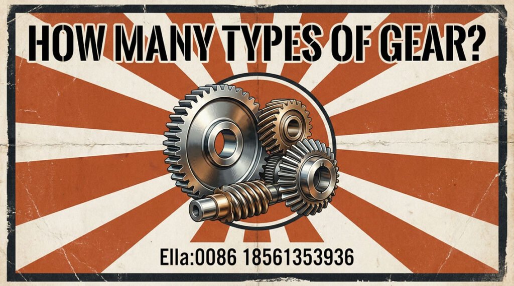
When engineers ask, “How many types of gears are there?”, the answer depends on how gears are classified. Gears can be categorized by tooth geometry, shaft arrangement, transmission configuration, manufacturing method, or industrial application.
The main industrial gear types include spur gears, helical gears, herringbone gears, bevel gears, worm gears, planetary gears, ring gears, and girth gears. Large industrial equipment also uses application-specific terms such as bull gears, mill gears, open gears, and gear-and-pinion sets.
For heavy machinery, however, identifying the gear type is only the starting point. Module, pitch diameter, pressure angle, face width, material, heat treatment, gear quality, tooth contact, alignment, and operating load determine whether a gear will perform reliably.
What Is a Gear and How Is It Classified?
A gear is a toothed mechanical component used to transmit rotational motion and torque between shafts. By changing tooth count and gear geometry, a gear pair can change speed, torque, rotational direction, or shaft orientation.
Important gear parameters include:
- Module: the metric parameter defining tooth size and closely related to pitch diameter and tooth count.
- Pitch diameter: the reference diameter used to define the fundamental geometry of a gear pair.
- Pressure angle: the angle associated with the tooth-force transmission geometry.
- Helix angle: the inclination of a helical tooth relative to the gear axis.
- Face width: the axial width over which the teeth engage.
- Backlash: the clearance between mating tooth flanks.
- Gear ratio: the relationship between the rotational speeds or tooth counts of mating gears.
Gears can therefore be classified according to tooth geometry, such as spur or helical; shaft arrangement, such as parallel or intersecting shafts; or application, such as mining mill gears or paper machine gears.
A single component can belong to several categories. For example, a large mining mill gear may be an external spur gear, a large module gear, an open gear, and a girth gear at the same time.
What Are the Main Types of Gears?
Spur Gears
Spur gears have straight teeth parallel to the gear axis. They are among the simplest cylindrical gear geometries and are used for parallel-shaft transmission.
Large spur gears are used in various industrial drives where their geometry is appropriate for the required load and speed. Their relatively straightforward tooth geometry can simplify manufacturing and inspection.
However, tooth engagement is less gradual than with helical gearing. At higher speeds or where smooth transmission is critical, the dynamic behavior and noise characteristics of spur gears must be evaluated as part of the complete design.
Helical Gears
Helical gears have teeth inclined relative to the gear axis. The inclined teeth engage progressively, generally producing smoother transmission than straight spur gearing.
Helical gears are widely used in industrial gearboxes, conveyors, process machinery, and heavy-duty drives. Their geometry can provide favorable load-carrying characteristics, but it also generates axial forces.
Consequently, a helical gear cannot be evaluated independently of its shaft, bearing arrangement, housing stiffness, and alignment.
Herringbone Gears
Herringbone gears combine two opposing helical tooth sets. The opposing helix directions can balance the axial forces generated by the two halves of the gear.
They are useful in applications requiring high torque transmission and smooth operation, particularly in heavy industrial machinery.
Because herringbone gears involve more complex tooth geometry and manufacturing requirements, gear alignment, tooth accuracy, and inspection become especially important.
Bevel Gears
Bevel gears transmit motion between intersecting shafts and are commonly used where the machine requires a change in shaft direction.
Straight bevel and spiral bevel gears have different tooth geometries and operating characteristics. Spiral bevel gears provide progressive tooth engagement and are used in applications where smooth transmission and load capacity are important.
Worm Gears
A worm gear set consists of a worm and a worm wheel. The arrangement can provide substantial speed reduction in a compact right-angle transmission.
Unlike many rolling-contact gear arrangements, worm gearing involves significant sliding. Consequently, lubrication, efficiency, heat generation, and material pairing are important design considerations.
Worm gears therefore require application-specific evaluation rather than selection based solely on their available reduction ratio.
Planetary Gears
A planetary gear system generally contains a sun gear, planet gears, and a ring gear. Depending on which member is fixed, driven, or used as the output, different speed and torque relationships can be obtained.
Planetary arrangements provide high torque density and compact packaging and are particularly important in high-power transmission systems such as wind turbine gearboxes.
Because several gears share the transmitted load, planetary gear design requires careful consideration of load sharing, carrier stiffness, bearing loads, alignment, gear accuracy, and tooth strength.
Ring Gears, Girth Gears, and Bull Gears
These terms are frequently used in industrial machinery but should not automatically be treated as separate fundamental gear geometries.
A ring gear can refer to an internal or external gear depending on the application. A girth gear generally refers to a large external gear mounted around the circumference of rotating equipment such as a rotary kiln, ball mill, or dryer.
Bull gear is an application-specific industrial term commonly encountered in equipment such as sugar mills and grinding mills. It generally describes the larger gear in a gear-and-pinion drive.
Therefore, “girth gear,” “bull gear,” and “ring gear” often describe the configuration or application of a gear, rather than completely different tooth geometries.
Industrial Gear Configurations: Open Gears, Gear-and-Pinion Sets, and Gearbox Gears
Industrial gears can also be classified according to how they are installed.
Open gears operate outside an enclosed gearbox and are commonly used on large rotating equipment. Examples include mill girth gears, kiln gears, dryer gears, and other large gear-and-pinion drives.
An open gear system normally consists of a large gear and a smaller pinion. The pinion transfers torque to the large gear, producing the required reduction and driving the rotating machine.
By contrast, gearbox gears operate inside an enclosed housing with controlled lubrication and integrated shafts and bearings. Their design must consider the complete transmission system rather than the gear pair alone.
For large open gears, alignment, runout, tooth contact, lubrication, mounting, and thermal effects can have a major influence on operating life.
How Industrial Gears Are Manufactured
Machined and Cut Gears
Industrial gears are manufactured through a sequence that may include blank preparation, machining, gear cutting, heat treatment, finishing, and inspection.
The appropriate cutting process depends on the gear geometry, module, tooth count, pitch diameter, face width, production quantity, and required accuracy.
After heat treatment, gears may require finishing operations to achieve the specified tooth geometry and quality.
For large industrial gears, dimensional inspection and tooth-contact verification are particularly important because manufacturing errors can affect load distribution across the gear face.
Forged Gears
Forging is a method of producing the gear blank or near-net shape; it is not a separate tooth geometry.
Forged blanks may be selected where the required mechanical properties and material integrity make them appropriate for heavily loaded applications. The final gear performance still depends on material grade, forging practice, heat treatment, machining, tooth geometry, and inspection.
Case-Hardened Gears
Case hardening is used when a gear requires high surface durability while retaining a tougher supporting core.
Carburizing followed by appropriate hardening and tempering is one established approach for case-hardened gears. The resulting properties depend on the material, heat-treatment process, effective case depth, surface condition, and subsequent finishing.
Material and heat treatment are directly connected to gear load capacity. ISO 6336-5 addresses material strength and quality considerations for cylindrical involute gears and recognizes the effects of material condition and heat treatment on allowable strength.
Industrial Gear Types by Application
Paper Mill Gears
Paper production equipment requires reliable continuous-duty power transmission. Paper mill gears, refiner gears, pulper gears, dryer cylinder gears, rewinder gears, calender gears, and paper machine drive gears may all have different operating requirements.
Paper machine gears generally require careful attention to alignment, smooth transmission, tooth accuracy, lubrication, and thermal stability.
For replacement projects, the original gear geometry should be verified rather than estimated. Relevant information can include tooth count, module, pressure angle, face width, bore or mounting dimensions, material, heat treatment, and operating conditions.
Rubber Machinery Gears
Rubber processing equipment can impose high torque and cyclic or shock loading on transmission components.
Applications include rubber mill gears, open mill gears, internal mixer gears, Banbury mixer gears, rubber refiner gears, calender gears, and rubber extruder gears.
Gear design should consider peak torque, load reversals, shaft stiffness, tooth-root strength, bearing loads, lubrication, and thermal conditions.
For rubber machinery gear replacement, matching only the outside dimensions is insufficient. The replacement gear must reproduce the functional tooth geometry and interface dimensions required by the existing drive.
Mining Gears
Mining equipment uses some of the largest and most heavily loaded industrial gear systems.
Ball mill gears, SAG mill gears, rod mill gears, mill pinions, mining girth gears, and mining mill open gears transmit high torque under demanding operating conditions.
The large gear and pinion must be considered as a matched system. Tooth contact, alignment, runout, lubrication, load distribution, and foundation or support conditions can all influence gear life.
Terms such as ball mill big gear, SAG mill big gear, mining mill bull gear, and mining girth gear generally describe application-specific large gears rather than fundamentally different tooth forms.
Cement Plant Gears
Cement plants rely extensively on large industrial gearing for rotating equipment.
Applications include rotary kiln girth gears, cement mill gears, vertical mill drives, roller press drives, and rotary dryer girth gears.
For large open gears, engineering attention should be given to pitch diameter, module, face width, tooth accuracy, gear-to-pinion alignment, lubrication, thermal effects, and tooth-contact pattern.
Replacement of a kiln or cement mill gear should therefore involve dimensional and geometric verification rather than simply copying an external diameter.
Sugar Mill Gears
Sugar production uses high-torque gear drives in cane preparation and milling equipment.
Common applications include sugar mill gears, sugar cane mill gears, sugar mill bull gears, mill pinions, cane crusher gears, cane shredder gears, and open gearing.
The large gear and pinion must withstand the actual torque and load variations of the process. Correct alignment, tooth strength, lubrication, and material/heat-treatment selection are important for long-term performance.
The terms crown gear and crown pinion are also encountered in sugar-mill applications and should be interpreted according to the particular machine design rather than assumed to describe a universal gear geometry.
Marine and Heavy-Duty Marine Gears
Large marine transmission systems require high reliability under variable operating conditions.
Relevant applications include large marine gears, marine main drive gears, marine reduction gears, ship main reduction gears, and custom large marine gears.
Marine gear design may involve requirements for vibration, noise, lubrication, corrosion protection, shaft alignment, and reliability. The applicable marine requirements should be established from the specific vessel and transmission system.
Specialized components such as dredger cutter-head gears or heavy-duty marine winch gears should likewise be specified according to the actual equipment duty rather than treated as generic marine gears.
Steel Mill Gears
Steel production contains numerous heavy-duty gear applications.
Examples include converter tilting gears, rolling mill gears, mill pinions, coiler and recoiler gears, caster drive gears, sinter plant gears, and large steel mill gears.
Steel mill drives can experience high torque, reversing loads, shock loading, and demanding thermal conditions. Gear tooth bending strength, surface durability, shaft stiffness, bearing capacity, alignment, and lubrication must therefore be evaluated together.
Crane and Port Crane Gears
Crane systems use gears for hoisting, travelling, luffing, and slewing.
Crane gears, slewing gears, slewing ring gears and pinions, hoist gears, luffing gears, port crane gears, and container crane gears can experience frequent acceleration, deceleration, braking, and load reversals.
For slewing systems, the slewing ring and pinion must be considered as a complete transmission. Tooth contact, backlash, alignment, mounting accuracy, and load distribution are critical.
Wind Turbine Gears
Wind turbines contain several distinct gear applications that should not be confused.
Inside the gearbox, planet gears, sun gears, and planetary ring gears form the drivetrain. Separately, the turbine may use external yaw gears, yaw ring gears and pinions, pitch gears, and pitch ring gears.
These systems operate under variable loading and require careful consideration of fatigue, lubrication, alignment, gear accuracy, and bearing loads.
For gearbox gearing, the design should be evaluated as part of the complete drivetrain. A replacement wind turbine gear cannot be specified reliably from dimensions alone.
Large Industrial Gears: Girth, Ring, and Large-Diameter Gears
Large industrial gears differ from small enclosed gearbox gears not simply because they are physically larger, but because their size makes manufacturing, assembly, alignment, and load distribution more demanding.
Important parameters include:
- Module and pitch diameter
- Tooth count and pressure angle
- Face width
- Tooth profile and lead
- Backlash
- Runout
- Material and heat treatment
- Gear accuracy
- Pinion alignment
- Lubrication
- Mounting and support conditions
A large module gear can transmit substantial torque, but module alone does not determine its load capacity. Material, face width, geometry, heat treatment, gear quality, speed, lubrication, and actual operating loads must all be considered.
For cylindrical spur and helical gears, ISO 6336 provides calculation methods for load capacity, including pitting resistance and tooth bending strength within its defined scope. ISO also explicitly notes that the calculation method does not by itself guarantee the performance of an assembled drive system.
Gear Materials, Heat Treatment, and Gear Quality
Industrial gear materials are selected according to load, fatigue requirements, manufacturing method, heat treatment, size, and operating environment.
Alloy steels are widely used for demanding industrial gears. Depending on the design, gears may be through-hardened, case-hardened, or subjected to other suitable heat-treatment processes.
For case-hardened gears, the objective is generally to obtain high surface durability while maintaining adequate core toughness. Heat-treatment quality is therefore part of the gear design, not merely a manufacturing afterthought.
Gear quality also requires a defined standard and quality grade. ISO and AGMA systems provide established approaches to gear accuracy and rating, but their terminology and grade systems should not be treated as automatically interchangeable.
Quick-Reference Table: Industrial Gear Applications and Typical Material/Heat-Treatment Considerations
| Application | Typical gear requirement | Material / heat-treatment consideration |
|---|---|---|
| Mining mill / girth gear | High torque and fatigue resistance | Alloy steel selected for load and manufacturing requirements; appropriate heat treatment |
| Cement kiln / mill | Heavy continuous duty and contact durability | Material and heat treatment selected for surface and bending strength |
| Sugar mill | High torque and fluctuating loads | Material and treatment matched to tooth-root and contact requirements |
| Steel mill | Shock and reversing loads | Tough material and suitable hardening strategy |
| Paper machine | Smooth continuous transmission | Material, accuracy, finishing, and alignment matched to duty |
| Wind turbine | Variable fatigue loading | Specialized material, heat treatment, and quality requirements |
| Crane / slewing system | Repeated starts, stops, and load changes | Material and surface treatment matched to contact and bending loads |
Common Industrial Gear Failure Modes
Industrial gear failure rarely results from tooth geometry alone. Loading, lubrication, alignment, material, heat treatment, manufacturing quality, and installation can interact.
Common failure mechanisms include:
- Pitting: fatigue damage caused by repeated contact stress.
- Micropitting: localized surface fatigue associated with the tooth-flank contact and lubrication conditions.
- Scuffing: severe adhesive surface damage associated with inadequate separation and unfavorable sliding/temperature conditions.
- Abrasive wear: progressive material removal caused by contaminants or unsuitable lubrication.
- Tooth-root fracture: bending fatigue or overload failure at or near the tooth root.
- Plastic deformation: permanent tooth-surface deformation under excessive load or unsuitable material conditions.
ISO 6336 contains calculation procedures for the load capacity of cylindrical spur and helical gears. Its series addresses areas including pitting resistance and tooth bending strength, while separate documents address phenomena such as scuffing and micropitting.
Failure analysis should therefore consider the tooth-contact pattern, lubrication condition, alignment, operating history, load spectrum, material, heat treatment, and manufacturing records.
How to Select the Right Industrial Gear
A practical gear-selection process should begin with the machine rather than the gear catalogue.
Consider:
- Application and operating environment
- Input power and operating speed
- Required output torque and speed
- Load characteristics and duty cycle
- Gear ratio
- Module, pitch diameter, and face width
- Material and heat treatment
- Gear accuracy and quality requirements
- Shaft, mounting, and alignment conditions
- Lubrication and maintenance requirements
For a large gear-and-pinion system, the gear should not be selected independently from the pinion. The pair must be compatible in tooth geometry, center distance, speed ratio, load capacity, and contact conditions.
Custom and Replacement Industrial Gears
Replacement gears require more engineering information than simply the outside diameter and tooth count.
Where possible, obtain:
- Original drawing or gear inspection report
- Tooth count
- Module
- Pressure angle
- Helix angle and hand, where applicable
- Pitch diameter
- Face width
- Bore, shaft, key, flange, or mounting dimensions
- Material
- Heat treatment
- Gear quality requirement
- Operating speed and torque
- Lubrication method
- Existing failure information
For girth gear replacement, mining gear replacement, paper machine gear replacement, rubber machinery gear replacement, or replacement industrial gears, reverse engineering should verify the actual tooth geometry and critical interfaces.
If the original gear has failed, the damaged component should not automatically be treated as an accurate dimensional reference. Wear, deformation, and previous repairs may have changed important dimensions.
How to Choose a Large Gear Manufacturer
For large and custom industrial gears, manufacturing capability should be evaluated beyond catalogue product range.
Important criteria include:
- Gear design and load-capacity calculation capability
- Large-diameter machining capacity
- Gear cutting and finishing capability
- Material traceability
- Heat-treatment control
- Gear inspection and measurement
- Tooth profile and lead inspection
- Runout and dimensional inspection
- Gear-and-pinion contact verification
- Quality documentation
- Experience with the target industrial application
For critical replacement gears, the manufacturer should be capable of understanding why the original gear failed, not simply reproducing its external dimensions.
Conclusion: Choosing the Right Gear Type for Industrial Machinery
There is no single fixed number of gear types because gears can be classified according to geometry, configuration, manufacturing method, or industrial application.
The fundamental types include spur, helical, herringbone, bevel, worm, and planetary gears, while industrial terminology adds application-specific categories such as girth gears, bull gears, ring gears, mill gears, open gears, and gear-and-pinion sets.
For large industrial machinery, the correct gear is determined by much more than its name. Module, pitch diameter, tooth geometry, material, heat treatment, gear quality, load, alignment, lubrication, and operating environment must all be considered.
This is particularly important for large gears used in mining mills, cement kilns, sugar mills, steel plants, paper machines, rubber machinery, marine transmissions, wind turbines, and port cranes.
A reliable gear is therefore the result of integrated engineering—from load calculation and material selection through manufacturing, heat treatment, inspection, installation, and alignment.
Frequently Asked Questions About Industrial Gears
What are the main types of industrial gears?
The main gear geometries include spur, helical, herringbone, bevel, worm, and planetary gears. Industrial applications also use terms such as girth gear, bull gear, ring gear, and open gear to describe particular configurations or applications.
What is the difference between a girth gear and a ring gear?
A girth gear generally refers to a large external gear mounted around rotating industrial equipment such as a kiln, mill, or dryer. “Ring gear” is a broader term that can refer to internal or external ring-shaped gears depending on the application.
What is a large module gear?
A large module gear is a gear manufactured with a relatively large metric module, meaning its teeth are correspondingly large. There is no universal module value at which every industry begins calling a gear “large module”; the term is application-dependent.
What type of gear is used in a ball mill?
Large grinding mills commonly use an open gear-and-pinion drive, typically consisting of a large girth gear and smaller pinion. The exact gear geometry and design depend on the mill, transmitted load, speed, layout, and manufacturer’s engineering requirements.
What is the difference between a bull gear and a pinion?
In a gear-and-pinion drive, the bull gear is generally the larger gear and the pinion is the smaller mating gear. Their tooth counts establish the speed ratio, while their geometry must be compatible for correct tooth engagement and load distribution.
What materials are used for large industrial gears?
Large industrial gears commonly use suitable alloy steels or other engineering materials selected according to load, fatigue requirements, manufacturing method, heat treatment, and operating conditions. The material should be specified together with the required heat-treatment condition rather than by material name alone.
What causes large girth gear failure?
Common causes include excessive or fluctuating loads, poor alignment, unsuitable tooth contact, inadequate lubrication, contamination, tooth fatigue, manufacturing errors, mounting problems, and insufficient maintenance. A proper failure analysis should identify the initiating mechanism rather than only the visible damage.
How do I measure a gear for replacement?
Important information includes tooth count, module, pressure angle, pitch diameter, face width, helix angle and hand where applicable, bore and mounting dimensions, material, heat treatment, and operating conditions. For critical gears, dimensional inspection and tooth-geometry verification are preferable to estimating dimensions from a damaged component.
How do I choose a large gear manufacturer?
Evaluate the manufacturer’s ability to perform gear engineering calculations, manufacture large-diameter components, control heat treatment, inspect tooth geometry, document material and quality, and verify gear-and-pinion contact. Experience with the specific application is also important.
Can a custom industrial gear be manufactured from an existing gear?
Yes, in many cases a replacement or custom gear can be engineered from an existing component, drawing, or inspection data. However, the original tooth geometry, material, heat treatment, mounting dimensions, and operating requirements should be verified rather than simply copying worn or damaged dimensions.