

Gears are fundamental components in mechanical power transmission. They transfer rotational motion between shafts, establish a defined speed relationship, transmit torque, and help machinery operate within its required load and motion range. From a compact gearbox to a large-diameter gear driving a mining mill, the underlying principles are similar, but the design requirements can differ significantly.
Understanding gears requires more than identifying their shapes. Engineers must consider tooth geometry, module, pitch diameter, material properties, manufacturing accuracy, lubrication, and operating loads. These factors determine whether a gear pair will mesh correctly, transmit power reliably, and achieve its intended service life.
This guide explains how gears work, compares the main gear types, introduces essential engineering parameters, and examines gear applications in mining, cement, sugar processing, rubber machinery, steel production, marine equipment, wind power, paper mills, and port cranes.
1. What Is a Gear?
A gear is a toothed mechanical component that transmits rotational motion and force through engagement with another toothed component. Gears can change rotational speed, torque, direction, and the relationship between connected shafts. They are used in gearboxes, industrial drives, lifting equipment, processing machinery, and many other mechanical systems.
A typical gear pair consists of a driving gear, which receives input motion, and a driven gear, which transfers motion to the next component. When a smaller gear drives a larger gear, the output speed decreases and the available torque ideally increases, subject to transmission losses.
Important gear terminology includes:
- Pinion: Usually the smaller gear in a meshing pair, although the term primarily describes its role in a transmission rather than an absolute size.
- Gear ratio: The relationship between the rotational speeds or tooth counts of meshing gears.
- Module: The metric measure of tooth size, expressed in millimetres.
- Pitch diameter: The reference diameter used to describe gear geometry and calculate transmission relationships.
- Pressure angle: The angle defining the direction of force transmission between mating teeth in the transverse plane for conventional involute gearing.
- Center distance: The distance between the axes of two meshing gears.
These parameters help engineers specify compatible gears and evaluate their performance under actual operating conditions.
2. How Do Gears Work?
Gear Meshing and Power Transmission
Gears transmit force through contact between their teeth. For two gears to mesh correctly, their tooth geometry must be compatible, including the applicable module or diametral pitch, pressure angle, and tooth form.
Different gear arrangements serve different shaft configurations:
- External gears mesh through their outer teeth and generally rotate in opposite directions.
- Internal gears mesh when the teeth of one gear engage with the inward-facing teeth of another; common arrangements rotate in the same direction.
- Rack-and-pinion systems convert rotational motion into linear motion.
- Planetary gear systems combine sun, planet, ring, and carrier components to achieve specific speed relationships in a compact arrangement.
For a simple external gear pair, the ideal speed relationship is determined by the number of teeth:
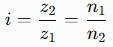
Here, z1 and z2 are the tooth counts of the driving and driven gears, while n1 and n2 are their respective rotational speeds. This convention defines the reduction ratio as input speed divided by output speed.
For example, a 20-tooth pinion driving a 60-tooth gear produces a 3:1 reduction ratio. If the input speed is 900 rpm, the ideal output speed is 300 rpm.
Speed, Torque, and Gear Ratio
A gear reduction lowers output speed while increasing available output torque. For an ideal transmission, torque multiplication is approximately equal to the reduction ratio. In a real system, friction, lubrication losses, bearing losses, and other inefficiencies reduce the actual output torque.
A simplified relationship is:
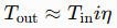
where T represents torque, i is the reduction ratio, and η is transmission efficiency expressed as a decimal.
However, gear ratio alone does not establish load capacity. Two gears with the same ratio may have very different capabilities because of differences in module, face width, material, heat treatment, tooth quality, and supporting shaft and bearing arrangements.
For heavy industrial machinery, engineers must evaluate the entire transmission system rather than selecting gears solely by speed ratio.
3. Main Types of Gears and Their Applications
Spur Gears
Spur gears have straight teeth parallel to the shaft axis and are commonly used between parallel shafts. Their geometry is relatively straightforward, making them widely used in industrial gearboxes, machine drives, and replacement gear assemblies.
Large spur gears can be found in heavy machinery where their size, load capacity, and tooth geometry suit the application. Correct alignment and adequate lubrication remain essential, especially when transmitting high torque.
Helical and Herringbone Gears
Helical gears have teeth inclined relative to the shaft axis. Their gradual tooth engagement can provide smoother operation than comparable spur gearing, although the inclined teeth generate axial thrust that the supporting system must accommodate.
Herringbone gears combine opposing helix directions to reduce or balance the net axial thrust generated by the two tooth sections. They may be used in demanding industrial transmissions where load capacity, smooth engagement, and shaft arrangement are important.
Applications include heavy-duty reducers, steel mill drives, and selected industrial power transmission systems.
Bevel, Worm, and Planetary Gears
These gear types serve different mechanical requirements:
- Bevel gears transmit motion between intersecting shafts, often at right angles.
- Worm gears transmit motion between non-parallel, non-intersecting shafts and can provide high ratios in a compact arrangement. Self-locking must not be assumed without appropriate analysis.
- Planetary gears use a central sun gear, planet gears, a carrier, and often an internal ring gear. Depending on which component is fixed, driven, or used as the output, planetary systems can provide different ratios and torque characteristics.
The appropriate arrangement depends on the required ratio, torque, efficiency, available space, shaft orientation, and duty cycle.
Internal Gears, Ring Gears, and Girth Gears
An internal gear has teeth cut on its inside circumference. Internal ring gears are common in planetary gearboxes, where they mesh with planet gears.
A girth gear, by contrast, is a large gear mounted around the circumference of equipment such as a rotary kiln or grinding mill. It typically meshes with a smaller pinion to drive the rotating equipment. Girth gears are often part of an open gear drive, although the exact arrangement depends on the machine design.
These terms should not be treated as interchangeable. Engineers specifying large industrial gears must identify the actual configuration, tooth geometry, mounting arrangement, and duty requirements.
Large-module gears, large-diameter gears, open gearing, and matched gear-and-pinion sets are common in heavy industrial applications where standard catalogue components may not meet the required dimensions or operating conditions.
4. Essential Gear Design Parameters and Engineering Terminology
Module, Tooth Count, and Pitch Diameter
For standard metric spur gears, the relationship between module, tooth count, and reference diameter is:
d=mz
where:
- d = reference diameter, in millimetres
- m = module, in millimetres
- z = number of teeth
Module indicates tooth size: for the same tooth count, a larger module produces a larger reference diameter. For two standard external spur gears with compatible geometry, the nominal center distance is:
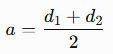
This relationship assumes standard reference geometry; profile shift and other design modifications can change the applicable center-distance calculation.
The outside diameter is not a substitute for pitch or reference diameter. Tooth count, module, pressure angle, profile modifications, and other geometric details must be checked when verifying gear compatibility.
Tooth Geometry, Gear Accuracy, and Load Capacity
Other important design parameters include:
- Pressure angle: Influences tooth force direction and gear geometry.
- Helix angle: Defines the inclination of helical teeth and affects axial force.
- Face width: The axial width of the toothed portion, influencing load distribution and capacity.
- Backlash: The clearance between mating teeth, necessary for proper operation under specified conditions.
- Contact ratio: Describes the average number of tooth pairs in contact during meshing and influences transmission smoothness.
Gear accuracy and load rating are related but different engineering considerations. ISO 1328 addresses accuracy classification for specified cylindrical gear types, while applicable AGMA standards provide methods and classifications for particular gear designs, accuracy requirements, or rating calculations. The correct standard and edition depend on the application and gear configuration.
A higher accuracy grade does not, by itself, guarantee greater load capacity. Capacity also depends on tooth-root strength, surface durability, material properties, lubrication, alignment, and service loads.
Materials, Heat Treatment, and Manufacturing
Gear materials and manufacturing routes must match the component’s dimensions, loads, production requirements, and service environment. Common choices include suitable grades of alloy steel and cast steel, with other materials used where the design and operating conditions permit.
Typical manufacturing and processing steps may include:
- Material selection and forging or casting, where appropriate.
- Rough machining and preparation of the gear blank.
- Tooth cutting or other suitable tooth-generation processes.
- Heat treatment to obtain the required material properties.
- Finish machining or tooth finishing, when specified.
- Dimensional, material, and tooth-quality inspection.
Case hardening can provide a hard, wear-resistant tooth surface supported by a tougher core, making it suitable for certain heavily loaded gears. It is not the default solution for every large gear; material section size, process capability, distortion, required hardness profile, and service loads must be considered.
For large gears, manufacturing quality must be evaluated alongside practical requirements such as transport, installation, alignment, and inspection access.
5. Common Gear Failure Modes and Maintenance Considerations
Typical Gear Damage
Gear damage often reflects a combination of operating conditions, lubrication, geometry, and installation quality.
Common failure modes include:
- Pitting: Surface fatigue that produces small pits in the tooth contact area.
- Scuffing: Damage associated with severe sliding contact, friction, and inadequate separation of the tooth surfaces by lubricant.
- Abrasive wear: Material removal caused by hard contaminants or abrasive contact.
- Tooth-root fatigue: Cracks developing under repeated bending stress.
- Tooth breakage: Potentially caused by overload, fatigue, impact, or an existing crack.
- Uneven contact or edge loading: Often associated with misalignment, deflection, mounting problems, or unsuitable contact geometry.
The same visible damage can have different underlying causes. Replacing a gear without investigating lubrication, alignment, load variation, and mating-component condition may result in repeat failure.
Inspection, Lubrication, and Replacement
Maintenance programs should reflect the machine’s operating environment and manufacturer’s recommendations. Depending on the equipment, inspections may include tooth-contact patterns, backlash, alignment, lubricant condition, vibration, temperature, and wear progression.
Before ordering a replacement gear, engineers should gather:
- Drawings or verified dimensions, including tooth count and reference diameter.
- Module or the applicable alternative tooth-size system, pressure angle, and tooth geometry.
- Face width, shaft or mounting interface, and center distance.
- Material, heat treatment, accuracy requirements, and inspection criteria.
- Input power, speed, torque, duty cycle, and relevant load conditions.
For large open gears and matched gear-and-pinion sets, the condition of the mating component and the mounting arrangement should also be considered.
6. How Gears Are Used in Major Industrial Applications
Mining and Cement Plants
Mining equipment uses gears in ball mills, SAG mills, rod mills, crushers, and associated drive systems. Large mill drives may use a girth gear and pinion, while other machines use enclosed gearboxes or different transmission arrangements. Gear selection must account for high torque, cyclic loads, abrasive environments, and the consequences of unplanned downtime.
Cement plants use gearing in rotary kilns, cement mills, vertical mills, roller presses, and other processing equipment. Rotary kiln girth gears and cement mill girth gears require suitable tooth geometry, mounting accuracy, lubrication, and contact distribution. Replacement projects should verify the original design and operating conditions rather than relying on external dimensions alone.
Sugar Mills and Rubber Machinery
Sugar processing machinery may use bull gears, crown gears, pinions, and other drive components in cane mills, crushers, and shredders. These gears transmit the torque required to process cane and must withstand the relevant load cycles, contamination, and maintenance conditions.
Rubber machinery uses gears in open mixing mills, internal mixers such as Banbury mixers, calenders, extruders, and refiners. Depending on the machine, gearing may coordinate roller speeds, drive mixing rotors, or transmit power through an enclosed gearbox. Replacement specifications must reflect the original transmission arrangement and the machine’s load and speed requirements.
Steel Plants and Heavy Industrial Equipment
Steel production involves a broad range of gearing, including rolling mill drive gears, pinion stand gears, coiler and recoiler gears, converter tilting gears, sinter plant gears, caster drives, and crane drives for handling heavy loads.
These applications may involve shock loads, repeated starts, variable operating speeds, high temperatures nearby, and demanding duty cycles. Engineers must consider load spectrum, shaft deflection, tooth-root strength, surface durability, alignment, and the quality of supporting components.
Marine, Dredging, and Shipyard Equipment
Marine and shipyard applications include ship main reduction gears, marine drive components, dredger cutter-head drives, winch gears, ship-lift drives, and heavy-duty crane gearing.
Enclosed marine reduction gearboxes differ from large exposed or specialized drive gears used on dredging and lifting equipment. Material selection, corrosion protection, lubrication, shock loads, maintenance access, and the consequences of equipment failure must be considered for each application.
Power Generation and Wind Turbines
Gears support power transmission in a range of power-generation systems. Wind turbines may use planetary gearboxes containing sun, planet, and internal ring gears, alongside separate yaw and pitch systems that position the nacelle or adjust the blades.
The terminology matters: a wind turbine planetary ring gear is not the same component as a yaw ring gear. Gearbox replacement, yaw pinion replacement, pitch-system repairs, and refurbishment each require identification of the relevant assembly and its operating requirements.
Paper Mills and Paper-Making Machinery
Paper machines use drive gearing in refiners, pulpers, dryer cylinders, Yankee dryers, calenders, and rewinders. Depending on the machine architecture, gears may transmit power to individual sections or support synchronized operation across connected equipment.
Paper machine heavy-duty gears must be suitable for continuous service, the required speed relationship, and the operating conditions of the specific section. When specifying dryer section drive gears or paper mill replacement gears, engineers should verify tooth geometry, mounting interfaces, alignment, lubrication, and the condition of connected drives.
Port Cranes and Lifting Equipment
Port, container, tower, crawler, and mobile cranes use various gear arrangements for slewing, hoisting, and luffing. Slewing ring gears and pinions enable crane rotation, while other gearboxes and gear sets support lifting and boom movement.
Because these systems operate with changing loads and frequent starts and stops, selection must account for load reversals, duty classification, backlash requirements, alignment, and coordination with braking and safety systems. Crane replacement gears should be verified against the actual machine design, not selected solely by nominal diameter or tooth count.
7. Quick-Reference Table: Gear Types, Materials, and Typical Applications
| Gear type or configuration | Common material or treatment options | Typical applications | Key engineering considerations |
|---|---|---|---|
| Spur and helical gears | Suitable alloy steels; heat treatment selected for load and wear requirements | Industrial gearboxes, rolling mill drives, machine transmissions | Tooth geometry, bending strength, surface durability, alignment |
| Herringbone gears | Suitable steels with application-specific heat treatment | Heavy-duty industrial transmissions | Opposing helix geometry, axial-force balance, manufacturing accuracy |
| Girth gears and pinions | Cast or forged steel options, depending on design and manufacturing route | Mining mills, cement mills, rotary kilns | Large-scale geometry, contact pattern, mounting, lubrication |
| Sugar mill bull gears and pinions | Suitable cast or forged materials selected for load and service environment | Cane mills, crushers, shredders | High torque, shock loads, tooth condition, contamination |
| Planetary gears and ring gears | Alloy steels and suitable heat treatments according to load and design | Wind turbine gearboxes, industrial reducers | Internal/external mesh compatibility, load sharing, bearing support |
| Slewing gears and pinions | Application-appropriate steels and corrosion protection where required | Port cranes, lifting equipment, slewing drives | Load reversals, backlash, mounting accuracy, duty cycle |
These are general engineering examples, not fixed material prescriptions. Final selection requires evaluation of the actual load case, geometry, manufacturing process, and service conditions.
8. How to Select or Specify a Custom Industrial Gear
Define the Operating Requirements
Start by documenting the operating requirements:
- Input and output speeds, power, torque, and required ratio.
- Duty cycle, load variation, shock loads, and starting conditions.
- Shaft arrangement, available space, mounting interfaces, and lubrication.
- Ambient conditions, contamination, corrosion exposure, and maintenance constraints.
Use these requirements to determine whether the application calls for a standard gear, custom large-module gear, open gear drive, or matched gear-and-pinion set.
Verify Geometry, Materials, and Manufacturing Quality
Confirm the gear’s tooth geometry, dimensions, material, heat treatment, accuracy requirements, and inspection method. Specify applicable ISO or AGMA criteria clearly, including the relevant standard where required.
For large-diameter gears, also assess blank manufacturing capability, tooth-cutting capacity, heat-treatment limitations, inspection methods, transport, installation, alignment, and access for future maintenance.
Choose a Gear Manufacturer for Replacement Projects
A capable industrial gear manufacturer should be able to review drawings, verify geometry, recommend technically justified manufacturing routes, control material and heat treatment, and provide dimensional and tooth-quality inspection records appropriate to the project.
For large industrial gears and replacement projects, evaluate the supplier’s experience with the specific gear configuration and application. Technical review, manufacturing capability, traceability, and installation compatibility are more meaningful selection criteria than price alone.
9. Frequently Asked Questions About Mechanical Gears
1. What is a gear, and what is its main function?
A gear is a toothed component that transmits motion and force through meshing teeth. Its main functions are to establish a defined speed relationship, transmit torque, and change the direction or arrangement of motion when required.
2. What are the main types of gears used in mechanical systems?
Common types include spur, helical, herringbone, bevel, worm, internal, and planetary gears. The appropriate type depends on shaft orientation, gear ratio, load, efficiency, available space, and operating conditions. Each family has its own tooth geometry and preferred shaft arrangement. Our guide on how many types of gears are used in industrial drives sets out the full list together with the applications that suit each one.
3. What is the difference between a gear and a pinion?
A pinion is generally the smaller gear in a meshing pair and often serves as the driving member. The word describes its role within the transmission; it does not mean that every pinion must drive a larger gear in every application.
4. What is the difference between module and pitch diameter?
Module measures metric tooth size and is defined for standard metric gearing by the reference diameter divided by tooth count. Pitch or reference diameter describes the gear’s reference size and, for a standard spur gear, equals module multiplied by tooth count.
5. How do you calculate the gear ratio of a gear pair?
For a simple meshing gear pair, the reduction ratio is the driven gear’s tooth count divided by the driving gear’s tooth count. Under the same ideal kinematic relationship, it equals input rotational speed divided by output rotational speed.
6. What is the difference between a ring gear and a girth gear?
A ring gear commonly refers to a gear with teeth on its inner or outer circumference, including internal gears used in planetary gearboxes. A girth gear is a large circumferential gear typically used to drive rotating equipment such as mills and rotary kilns.
7. Which materials are commonly used for heavy-duty industrial gears?
Suitable alloy steels and cast steels are common choices, depending on the component’s size, geometry, load, manufacturing route, and service environment. Heat treatment, including case hardening where appropriate, is selected according to the required surface durability and core properties.
8. What causes industrial gears to wear, pit, or break?
Common causes include inadequate lubrication, contamination, overload, repeated fatigue, misalignment, poor contact distribution, and unsuitable material or heat treatment. Accurate diagnosis should consider the damaged teeth, mating gear, lubrication system, mounting, and actual operating loads.
9. What information is required to manufacture a custom replacement gear?
Provide drawings or verified dimensions, tooth count, module or other tooth-size system, pressure angle, reference diameter, face width, material, heat treatment, accuracy requirements, mounting details, and operating loads. Existing gear inspection and mating-component information can help verify the specification.
10. How do you choose a manufacturer for large industrial gears?
Evaluate engineering support, experience with the required gear type, manufacturing and heat-treatment capabilities, dimensional inspection, material traceability, and ability to verify the design against operating conditions. For replacement gears, the supplier should also consider mating components, installation, alignment, and service requirements.
Gears are not interchangeable simply because they have similar dimensions or tooth counts. Reliable mechanical gearing depends on compatible geometry, adequate load capacity, appropriate materials and manufacturing, and correct installation and lubrication. For large industrial drives—from mining mill girth gears to sugar mill bull gears, paper machine drives, and crane slewing systems—engineering verification is essential to achieving dependable performance and long service life.Engineering references: ISO 1328-1 defines a flank-tolerance classification system for individual cylindrical involute gears; its tolerance classes should not be used alone to predict assembled transmission performance.