

Pressure angle is a fundamental parameter in involute gear design. It defines the geometry of the tooth profile and the direction in which force is transmitted between mating teeth. It therefore affects tooth strength, radial separating force, contact ratio, bearing loads, and the compatibility of gears within a transmission.
For engineers designing or replacing industrial gears, pressure angle must be considered alongside module, tooth count, reference diameter, face width, material, heat treatment, and manufacturing accuracy. This is particularly important for large spur gears, helical gears, girth gears, and gear-and-pinion sets used in heavy machinery.
This guide explains how pressure angle works, compares common values, examines its effects on gear performance, and covers practical considerations for mining, cement, sugar, rubber machinery, steel plants, marine equipment, wind turbines, paper mills, and port cranes.
1. What Is Pressure Angle in a Gear?
The pressure angle (α) is a geometric parameter of an involute gear tooth that defines the direction of the tooth-contact force relative to the tangent to the reference circle at the reference point. Equivalently, in the standard transverse geometry of involute gearing, it is the angle between the line of action and the common tangent to the reference circles at the pitch point.
The line of action is the direction along which the normal contact force acts between mating involute teeth. Pressure angle is therefore not simply the visible slope of a tooth flank.
Key terms include:
- Reference pressure angle: The angle specified for the gear’s reference geometry and tooth system.
- Operating pressure angle: The effective pressure angle of a mating gear pair at its actual operating center distance.
- Line of action: The line along which the tooth-contact force acts in an involute mesh.
- Helix angle: The inclination of a helical tooth relative to the gear axis; it is distinct from pressure angle.
- Module: A metric measure of tooth size, defined for standard cylindrical gearing by reference diameter divided by tooth count.
Pressure angle affects the involute profile and force direction, but it does not independently determine load capacity. Material strength, tooth dimensions, contact conditions, lubrication, alignment, and operating loads must also be evaluated.
2. How Does Gear Pressure Angle Work?
Line of Action and Tooth Contact
In involute gearing, the common normal at the point of tooth contact follows a straight line called the line of action. The contact point moves along the path of contact as the gears rotate, while the force direction remains aligned with the line of action for the ideal involute mesh.
The reference pressure angle describes the specified tooth geometry at the reference condition. The operating pressure angle depends on the actual operating center distance and the geometry of the mating gears. For a compatible involute pair, a change in center distance changes the operating pressure angle and can affect backlash and contact conditions.
These distinctions matter when installing or replacing gears. A gear pair that was designed for one center distance should not be assumed to retain the same operating conditions after changes to the housing, bearings, shafts, or mounting arrangement.
Pressure Angle and Gear Force Calculation
For a conventional spur gear, the tangential force transmits torque. The contact force also has a radial component that tends to separate the two gears.
The basic relationships are:
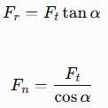
where:
- Ft = tangential force at the reference circle under the applicable reference-geometry assumptions
- Fr = radial separating force
- Fn = normal contact force
- α = pressure angle
For the same tangential force, increasing pressure angle increases the radial force and the normal contact force. The resulting loads must be accommodated by shafts, bearings, housings, and supporting structures.
Helical gears introduce an additional axial force component because of their helix angle. Their force analysis must account for the relevant normal and transverse geometry rather than applying spur-gear equations without adjustment.
3. Common Gear Pressure Angles and Their Differences
14.5°, 20°, and 25° Pressure Angles
Several nominal pressure angles appear in gear designs, including 14.5°, 20°, and 25°. The appropriate value depends on the gear standard, tooth proportions, manufacturing requirements, and application.
- 14.5°: Found in some legacy gear designs. Compared with a 20° design of otherwise similar standard proportions, it generally has a thinner tooth root and a base circle closer to the root, making undercutting more of a concern for certain low-tooth-count gears.
- 20°: Widely used in modern involute cylindrical gearing, offering a practical balance between tooth geometry, strength, and compatibility with common gear systems.
- 25°: Used in some gear systems where the design benefits from the associated tooth geometry and force characteristics. It produces a larger radial force than a lower pressure angle for the same tangential force.
These are not interchangeable options for an existing gear. Changing the pressure angle changes the tooth profile and base-circle geometry, so mating gears must be designed as a compatible pair. A nominally higher pressure angle does not automatically make a gear better for every application. (Elements of Metric Gear Technology, SDP/SI)
Standard Pressure Angle vs. Operating Pressure Angle
The reference pressure angle belongs to the specified gear geometry. The operating pressure angle describes the effective geometry when a mating pair runs at its actual center distance.
For an involute gear pair, the operating pressure angle can differ from the reference value if the operating center distance differs from the reference center distance. This change can affect operating pitch geometry, backlash, and contact conditions.
When inspecting an existing transmission, engineers should not infer the original reference pressure angle solely from the current operating center distance. Gear wear, backlash adjustments, profile modifications, and mounting changes can complicate the assessment.
4. How Pressure Angle Affects Gear Performance
Tooth Strength and Contact Ratio
Pressure angle influences tooth shape, including the base-circle diameter and the thickness distribution through the tooth profile. For standard full-depth involute teeth, a higher pressure angle generally produces a thicker tooth root than a lower pressure angle of otherwise comparable geometry. This can improve bending strength in some designs.
However, pressure angle also influences the path of contact and transverse contact ratio. A design with fewer tooth pairs sharing the load during portions of engagement may experience greater load variation and less smooth transmission. The actual result depends on tooth count, module, addendum, profile shift, center distance, and the geometry of both mating gears.
Engineers should evaluate both tooth-root bending strength and surface durability using suitable gear-rating methods. Selecting pressure angle solely to increase tooth thickness can overlook contact ratio, interference, noise, and bearing-load consequences.
Radial Force, Bearings, and Shaft Loads
Pressure angle directly influences the radial separating force in a conventional spur gear mesh. For a given tangential force, a higher pressure angle produces a higher radial force.
This affects the design of:
- Shafts and their bending loads.
- Bearings and bearing life.
- Gearbox housings and supporting structures.
- Mounting arrangements and alignment control.
These effects become important in heavy-duty reducers, large gear-and-pinion systems, and industrial drives transmitting high torque. In a large girth gear installation, for example, tooth geometry must be evaluated alongside pinion support, gear mounting, alignment, and the load distribution across the face width.
For helical gears, axial force must also be considered. Bearing selection and housing design should reflect the complete force system rather than pressure angle alone.
Efficiency, Noise, and Operating Reliability
Pressure angle can influence the geometry of tooth engagement, sliding conditions, and the variation of load during meshing. These factors can affect vibration and noise, but pressure angle is not a standalone predictor of efficiency or acoustic performance.
Other important factors include:
- Tooth accuracy and surface finish.
- Lubricant type, delivery, and operating temperature.
- Gear alignment and shaft deflection.
- Tooth modifications and backlash.
- Rotational speed and transmitted load.
Reliable gear design requires balancing strength, smooth engagement, manufacturing constraints, and support-system loads. A pressure angle selected for one objective may introduce trade-offs elsewhere.
5. Pressure Angle Compatibility, Module, and Gear Standards
Why Mating Gears Need Compatible Pressure Angles
Conventional involute external gears generally require compatible pressure angles, module or tooth-size system, and tooth geometry to mesh as intended. Matching tooth count or outside diameter is not enough.
Combining gears with incompatible pressure angles can lead to poor contact, incorrect backlash, interference, concentrated loading, accelerated wear, or premature tooth damage. A gear pair may appear to engage during a basic fit check but still have unsuitable contact geometry under load.
When replacing one gear in an existing drive, engineers should verify the mating gear’s geometry and condition. If a replacement design changes the pressure angle, both gears and the operating arrangement may need to be redesigned and revalidated.
Pressure Angle, Module, and Pitch Diameter
Module and pressure angle describe different aspects of gear geometry.
For a standard metric cylindrical gear:
m=d/z
where m is module, d is reference diameter, and z is tooth count.
Module establishes the scale of the teeth relative to tooth count, while pressure angle defines the involute tooth geometry and force direction. Both must be specified correctly for compatible mating gears. For our custom large module spur gears, module and pressure angle are specified together with tooth count, face width, and material to guarantee correct meshing with the mating pinion.
ISO 1328-1 addresses flank-tolerance classification for specified cylindrical involute gears. Applicable AGMA standards may be used for relevant gear accuracy or rating calculations. These standards address defined aspects of gear design and evaluation; neither a quality grade nor a pressure-angle designation alone establishes the load capacity of a complete transmission.
Pressure Angle in Spur, Helical, Bevel, and Worm Gears
For spur gears, the transverse and normal pressure angles are equal. For helical gears, they differ because the teeth are inclined relative to the shaft axis. For precision helical gear customization, engineers must specify the normal and transverse pressure angles together with the helix angle so the pair runs with the intended contact pattern and axial-force balance:

where αn is the normal pressure angle,αt is the transverse pressure angle, and β is the reference helix angle.
Bevel and worm gears require geometry-specific definitions and calculation methods. Engineers should verify the applicable reference planes and terminology rather than directly applying spur-gear equations to every gear type.
6. Pressure Angle in Heavy-Duty Industrial Gear Applications
Mining and Cement Mill Gears
Mining and cement machinery may use large girth gears, mill pinions, and other heavy-duty gear arrangements. Pressure angle affects the tooth-contact force direction, so it contributes to the loads transmitted through the pinion shaft, bearings, and supporting structure.
For ball mills, SAG mills, rod mills, cement mills, and rotary kilns, engineers must consider pressure angle together with module, tooth count, face width, material, lubrication, alignment, and the actual load spectrum. During girth gear replacement, the original tooth geometry and mating-pinion compatibility should be verified rather than inferred from gear diameter alone.
Sugar Mills and Rubber Machinery
Sugar mill bull gears, cane mill pinions, crushers, and shredders transmit substantial torque through machinery that may experience fluctuating loads. Their pressure angle must match the intended tooth system and be considered in the calculation of tooth forces and support loads.
Rubber machinery—including open mixing mills, internal mixers, Banbury mixers, calenders, refiners, and extruders—uses different gear arrangements depending on the machine. For replacement rubber machinery gears, engineers should verify the mating tooth geometry, backlash, duty cycle, and load requirements. The correct pressure angle is part of the design specification, not a parameter that can be selected independently during installation.
Steel Plants and Heavy Industrial Drives
Steel plants use gears in rolling mills, pinion stands, coilers, recoilers, converter tilting drives, sinter plants, and heavy-duty material-handling systems. These applications may experience reversing loads, shock loads, and frequent starts or stops.
Pressure angle influences tooth force direction and root geometry, while the overall design must address fatigue strength, surface durability, alignment, and bearing loads. Gear geometry and support-system design should be evaluated together, particularly where downtime has substantial operational consequences.
Marine, Port Cranes, and Lifting Systems
Marine reduction gear components, dredger cutter-head drives, winches, crane hoist systems, luffing drives, and slewing gear-and-pinion assemblies have different load and operating requirements.
For port cranes and other lifting systems, pressure-angle compatibility must be considered alongside load reversals, duty classification, backlash, mounting stiffness, and the requirements of associated braking and safety systems. A replacement slewing pinion, for example, must match the actual ring gear and drive geometry—not simply its nominal diameter.
Wind Turbines, Power, and Paper Mills
Wind turbines use different gear designs in planetary gearboxes, yaw drives, and pitch systems. The pressure-angle specification must correspond to the particular gear arrangement, including the relevant normal or transverse geometry for helical teeth where applicable.
Paper machine drive gears for refiners, pulpers, dryer cylinders, Yankee dryers, calenders, and rewinders must likewise match the specified tooth geometry. Continuous operation makes accurate replacement and alignment important, but pressure angle must be assessed alongside lubrication, wear, material condition, and the requirements of the complete drive.
7. Quick-Reference Table: Pressure Angle Effects and Engineering Checks
| Gear type or application | Pressure-angle considerations | Key engineering checks |
|---|---|---|
| Spur gears | Determines force direction and contributes to tooth geometry | Reference pressure angle, module, tooth count, backlash |
| Helical gears | Normal and transverse pressure angles differ | Helix angle, specified pressure-angle plane, axial force |
| Mining mill girth gears | Influences pinion and support-system loads | Mating geometry, alignment, contact pattern, lubrication |
| Planetary gears | Must be compatible across the relevant internal and external meshes | Tooth system, geometry, load sharing, assembly constraints |
| Crane slewing gears | Affects tooth forces under variable and reversing loads | Ring gear compatibility, backlash, mounting, duty cycle |
| Paper machine drive gears | Must match the intended tooth system for continuous operation | Reference geometry, accuracy, alignment, replacement fit |
The table summarizes design considerations rather than prescribing a pressure angle. Actual forces and gear capacity must be calculated from the specific gear geometry and operating conditions.
8. How to Identify or Specify the Correct Gear Pressure Angle
Identifying Pressure Angle on Existing Gears
The most reliable starting point is the original drawing, gear specification, or manufacturer documentation. If these are unavailable, a gear inspection specialist can determine the likely geometry using suitable measurements and engineering analysis.
Do not estimate pressure angle from tooth appearance alone. A proper identification process may require verification of:
- Gear type and tooth count.
- Module or applicable tooth-size system.
- Reference diameter and tooth thickness.
- Tooth profile and pressure angle.
- Helix angle and normal/transverse definitions, where applicable.
- Mating-gear geometry and operating center distance.
The module is the first of those to settle: once it is known, reference diameter follows from tooth count, and our guide on module in gear sets out the calculation along with the errors that distort a reading taken from a worn tooth. Existing wear, modified teeth, and changes to the mounting arrangement can complicate identification. Where the gear is critical to machine operation, measurement and engineering verification are preferable to an unconfirmed assumption.
Specifying Pressure Angle for Custom or Replacement Gears
When ordering a custom industrial gear, provide the pressure angle together with the full tooth geometry and application requirements. Useful information includes:
- Gear type, module, tooth count, and reference diameter.
- Reference pressure angle and, for helical gears, the relevant normal or transverse definition.
- Face width, tooth thickness, backlash requirements, and mounting dimensions.
- Material, heat treatment, and required accuracy or inspection criteria.
- Input speed, torque, duty cycle, operating environment, and mating-component information.
A qualified gear manufacturer should confirm compatibility with the mating gear and review the load and manufacturing requirements before production. For large-diameter gears, girth gears, and replacement gear-and-pinion sets, this verification helps prevent fit-up problems and unsuitable tooth contact.
9. Frequently Asked Questions About Gear Pressure Angle
1. What is pressure angle in a gear?
Pressure angle is a geometric parameter that defines the direction of the normal tooth-contact force relative to the tangent at the reference point in conventional involute gearing. It affects tooth geometry, radial force, and mating-gear compatibility.
2. What is the most common pressure angle for gears?
A 20° reference pressure angle is widely used in modern involute cylindrical gearing. Other values occur in legacy and specialized designs, so the correct angle must be confirmed from the gear specification.
3. What is the difference between 14.5° and 20° pressure angle?
For otherwise comparable standard gear geometry, a 20° pressure angle generally produces a thicker tooth root and a higher radial separating force for the same tangential load. A 14.5° design may have different contact and undercutting characteristics, so the two should not be substituted without checking the complete gear geometry.
4. How does pressure angle affect gear tooth strength?
Pressure angle influences tooth-root thickness, involute geometry, and contact ratio. A higher angle can improve tooth-root strength in some standard designs, but actual strength depends on module, tooth count, profile modifications, material, face width, and operating loads.
5. How does pressure angle affect radial force and bearing loads?
For a conventional spur gear, radial force is Fr=Ft*tanα. At the same tangential force, a higher pressure angle produces a greater radial separating force, which increases the loads that shafts, bearings, and housings must support.
6. Can gears with different pressure angles mesh together?
Conventional involute gears with different reference pressure angles are generally not compatible as a standard mating pair. A specially engineered arrangement may be possible, but it requires verification of tooth geometry, contact conditions, and operating requirements rather than assuming interchangeability.
7. What is the difference between reference and operating pressure angle?
The reference pressure angle belongs to the specified gear geometry. The operating pressure angle describes the effective geometry of a mating pair at its actual center distance, which can differ from the reference condition.
8. How does pressure angle differ between spur and helical gears?
For spur gears, normal and transverse pressure angles are equal. For helical gears, they differ because the teeth are inclined to the shaft axis, so the specified pressure-angle plane must be identified when designing or replacing the gear.
9. How do you identify the pressure angle of an existing gear?
Start with original drawings, manufacturer records, or gear specifications. If those are unavailable, use appropriate gear metrology and engineering analysis, checking tooth count, module, tooth thickness, profile geometry, and mating-gear information rather than relying on visual estimates.
10. What pressure-angle information is needed to manufacture a replacement industrial gear?
Provide the reference pressure angle and its applicable definition, together with gear type, module or tooth-size system, tooth count, reference diameter, face width, material, heat treatment, accuracy requirements, and operating loads. For helical gears, specify the relevant normal or transverse geometry and helix angle.
Pressure angle is a core gear-design parameter because it affects both tooth geometry and the forces transmitted through a gear mesh. For reliable industrial gearing, it must be considered alongside module, tooth count, material, manufacturing accuracy, lubrication, and support-system design.
Whether specifying a large girth gear for a mining mill, a bull gear for a sugar mill, a paper machine drive gear, or a slewing pinion for a port crane, verify the complete mating geometry rather than treating pressure angle as an isolated specification.