

Gear ratio is one of the fundamental parameters in mechanical power transmission. It defines the relationship between the rotational speeds of connected gears and helps engineers determine how a drive system converts input speed into output speed and torque.
In industrial machinery, gear ratio calculations are essential when designing gearboxes, selecting motor speeds, specifying gear and pinion sets, and replacing worn components. Applications range from paper machine drive gears and rubber mill transmissions to large mining mill gears, cement kiln girth gears, marine reduction gear sets, and wind turbine gearboxes.
However, calculating a ratio is only the first step in transmission design. Engineers must also consider efficiency, load capacity, gear geometry, duty cycle, and the mechanical arrangement of the complete drive.
1. What Is Gear Ratio?
Gear ratio describes the rotational relationship between the input and output members of a gear transmission. For a simple external gear pair, it is commonly expressed as the number of teeth on the driven gear divided by the number of teeth on the driving gear.
A gear ratio determines whether the driven gear rotates more slowly or more quickly than the driving gear:
- Reduction ratio: The output rotates more slowly than the input, generally increasing output torque.
- Speed-increasing ratio: The output rotates faster than the input, generally reducing output torque.
- 1:1 ratio: The input and output speeds have equal magnitudes.
Consider a small pinion driving a larger gear. The larger gear has more teeth and takes more input revolutions to complete one revolution, resulting in speed reduction. This principle applies to simple gear pairs and to individual stages in larger industrial transmissions.
In heavy machinery, a large girth gear and its mating pinion may form one reduction stage. The complete machine’s drive ratio, however, may also include a gearbox, motor coupling, or additional gear stages.
It is important to define the ratio convention before calculating or comparing specifications. In this article, the reduction ratio is defined as input speed divided by output speed, so a reduction greater than 1 indicates that the output is slower.
2. Gear Ratio Formula: The Basic Equations
Formula 1: Gear ratio from tooth count
For a simple pair of compatible meshing gears:
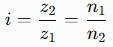
Where:
- i = reduction ratio
- z1 = number of teeth on the driving gear
- z2 = number of teeth on the driven gear
- n1 = input rotational speed
- n2 = output rotational speed
For example, if a 20-tooth pinion drives a 60-tooth gear:
i=60/20=3
The reduction ratio is 3:1. If the input rotates at 900 rpm, the ideal output speed is:
n2=900/3=300rpm
For a simple external gear pair, the driven gear rotates in the opposite direction to the driver. The ratio above describes the magnitude of the speed relationship; a signed ratio can be used when rotational direction must be represented mathematically.
Formula 2: Gear ratio from pitch diameter
For compatible meshing gears, the ratio can also be calculated from their reference pitch diameters:

Here, d1 and d2 are the respective reference pitch diameters of the driving and driven gears.
For standard external spur gears with compatible geometry, the pitch diameter is related to module and tooth count by:
Where d is the reference pitch diameter, m is the module, and z is the number of teeth. This relationship helps engineers verify gear dimensions and mating compatibility.
Practical recommendation: Use tooth counts whenever they are known. Pitch-diameter calculations are useful for checking drawings and evaluating existing equipment, but outside diameter should not be substituted directly for pitch diameter.
3. How to Calculate Gear Ratio Step by Step
Example 1: Calculate the ratio from tooth counts
Suppose a driving pinion has 24 teeth and the driven gear has 72 teeth.
Step 1: Identify the driving and driven gears.
- Driving pinion: z1=24
- Driven gear: z2=72
Step 2: Apply the formula.
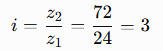
The reduction ratio is 3:1.
Step 3: Calculate output speed.
If the input speed is 1,200 rpm:
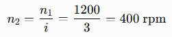
The driven gear rotates at 400 rpm in the opposite direction to the driving gear, assuming a simple external gear pair.
Example 2: Calculate the overall ratio of a multi-stage gearbox
Industrial gearboxes often contain several stages. For a conventional arrangement with a consistent reduction-ratio convention, multiply the ratios of the individual stages:

Suppose a gearbox has two reduction stages:
- First stage: 3:1
- Second stage: 4:1
The overall ratio is:

With an input speed of 1,440 rpm, the ideal output speed is:
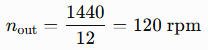
This method is useful when evaluating multi-stage reducers, marine reduction gear sets, and wind turbine gearboxes. For more complex arrangements involving planetary trains or differential motion, the kinematics of each stage must be established before calculating the overall ratio. For drives that combine planetary and parallel stages, our guide on how to calculate gear ratio works through each stage separately before they are combined.
4. Gear Ratio, Speed, Torque, and Power
Gear ratio affects output speed and torque, but it does not create power. The relationship between input and output depends on the ratio and the losses in the transmission.
Output speed
For a reduction ratio defined as input speed divided by output speed:
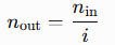
A higher reduction ratio produces a lower output speed when input speed remains constant.
Output torque
For a reducing transmission, approximate output torque can be calculated as:
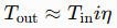
Where:
- Tin= input torque
- Tout = output torque
- i = reduction ratio
- η = transmission efficiency, expressed as a decimal
For example, if input torque is 100 N·m, the reduction ratio is 5:1, and transmission efficiency is 95%:

This is an illustrative calculation, not a design rating. Actual performance depends on the transmission’s operating conditions and the efficiency value applicable to the duty point.
Power and efficiency
Rotational mechanical power can be expressed as:
P=Tw
Where P is power, T is torque, and w is angular velocity. In real gear systems, output power is lower than input power because of losses in gear meshes, bearings, seals, and other components.
When selecting a gearbox, engineers should therefore evaluate the ratio alongside required output torque, speed, efficiency, thermal capacity, and operating duty. A suitable ratio alone does not demonstrate that the gears can carry the load safely.
5. Gear Ratio in Different Gear Types
The basic tooth-count formula applies directly to a simple gear pair, but the calculation changes when the transmission architecture becomes more complex.
Spur and helical gears
For a simple external spur gear pair, the ratio is the driven gear’s tooth count divided by the driving gear’s tooth count. A compatible helical gear pair follows the same tooth-count relationship for its rotational-speed ratio.
For helical gears, the reference geometry must account for the helix angle and the specified module system. Engineers should not infer tooth compatibility from module alone without checking the relevant geometry and pressure angle.
Bevel gears
Bevel gears transmit motion between intersecting shafts in typical arrangements. Their ratio can be calculated from the tooth counts of the driving and driven gears, but shaft angle, tooth geometry, and the intended mounting arrangement must also be considered.
Worm gear sets
For a simple worm drive, the nominal ratio is:

Here, Zwheel is the number of teeth on the worm wheel and Sworm is the number of starts on the worm. The number of worm starts—not the number of worm threads counted without regard to their starts—is the relevant quantity.
Planetary gear trains
Planetary gearboxes contain a sun gear, planet gears, a ring gear, and a carrier. The ratio depends on which member is fixed, which member is the input, and which member is the output. There is no single tooth-count ratio that applies to every planetary arrangement.
For a common simple planetary arrangement with the ring gear fixed, the sun gear as input, and the carrier as output:

Where Zr is the ring gear’s tooth count and Zs is the sun gear’s tooth count. Other arrangements require the appropriate kinematic relationship.
Rack-and-pinion systems
A rack-and-pinion converts rotational motion into linear motion. Its relationship is usually expressed as linear travel per pinion revolution rather than as a conventional output-shaft gear ratio. For an ideal pinion, travel per revolution equals the circumference of its reference pitch circle.
6. Industrial Gear Ratio Applications Across Major Industries
Gear ratio calculations help engineers translate process requirements into the speeds and torques needed at a machine’s working components. The correct ratio depends on the machine’s drive architecture, not just its industry.
6.1 Mining and Cement Equipment
Ball mills, SAG mills, rod mills, crushers, cement mills, and rotary kilns require drive arrangements matched to their rotational speed, starting torque, and operating loads.
For a conventional girth gear and pinion pair, the tooth-count ratio establishes the speed relationship between the pinion and the large gear. The overall drive ratio must also account for any gearbox stages between the motor and pinion.
When specifying ball mill gear replacement, SAG mill girth gear replacement, or rotary kiln girth gear replacement, engineers should verify the existing tooth counts, module or applicable tooth system, pitch diameter, and mating geometry. Ratio matching alone is not sufficient to confirm replacement compatibility.
6.2 Sugar Mills and Cane Processing
Sugar mill drives may use bull gears, pinions, and other open gear arrangements to deliver the required roller speed and torque. The selected ratio must suit the process speed, mechanical loading, and upstream drive arrangement.
For a cane mill bull gear and pinion, calculate the ratio from the mating tooth counts, then account for any upstream reduction stages. A replacement gear must preserve the required ratio while also meeting the original geometry, load capacity, and installation requirements.
6.3 Rubber Machinery
Open mixing mills, Banbury internal mixers, rubber calenders, and extruders have different drive requirements. Some mixing mills use differential roller speeds, meaning the two rolls operate at different rotational speeds according to the process design.
In these systems, the ratio between the relevant gears must be considered alongside the machine’s overall transmission ratio. When planning rubber mill drive gear or internal mixer gear replacement, verify the original drive arrangement and required speed relationships rather than assuming every gear pair is intended to provide the same reduction.
6.4 Steel Plants and Rolling Mills
Rolling mills, pinion stands, coilers, recoilers, converter tilting systems, and other steel plant equipment use transmission ratios to achieve their required operating speeds and torque.
For a rolling mill drive, the ratio must be considered with motor speed, roll speed, and any intermediate gearbox stages. Large steel mill gears and mill pinion gears must also be selected for the relevant loading, tooth geometry, and operating duty.
6.5 Marine and Port Crane Systems
Marine reduction gear sets reduce prime-mover speed to the speed required by the driven equipment. Crane hoists, luffing mechanisms, and slewing systems also use gear ratios to control motion and deliver the required torque.
A port crane slewing ring gear and pinion provide a ratio determined by their tooth counts, but the complete drive may include a motor and gearbox. Engineers must distinguish the local ring-gear-and-pinion ratio from the overall ratio between motor and slewing structure. Safety-critical lifting and holding requirements must be evaluated separately.
6.6 Wind Turbines and Power Generation
Wind turbine gearboxes can combine planetary and parallel-shaft gear stages to convert rotor speed to the speed required by the generator. The overall gearbox ratio is the product of the individual stage ratios when each stage is represented as a conventional reduction.
Planetary stages require the correct kinematic equation for their fixed, input, and output members. Wind turbine yaw and pitch systems are separate positioning mechanisms and should not be confused with the main power-transmission ratio.
6.7 Paper Mills and Paper Machines
Paper machine drive gears coordinate the speeds of sections that process and transport the paper web. Dryer cylinder drives, Yankee dryer drives, calenders, rewinders, refiners, and pulpers have different speed and torque requirements.
When specifying paper machine gear replacement, engineers should establish whether the required ratio belongs to a single gear pair, a section drive, or a complete gearbox. The ratio must support the process speed while maintaining compatibility with the existing drive and control system.
6.8 General Power Transmission and Heavy Industrial Gearboxes
Large spur gears, helical gears, herringbone gears, reducers, and custom gearbox gears are used in many heavy industrial applications. Their ratios are calculated from the appropriate gear arrangement, but their design also depends on transmitted load, module, face width, material, heat treatment, and manufacturing accuracy.
For custom industrial gears or large gear and pinion sets, a manufacturer needs enough information to establish the intended ratio and confirm that the proposed geometry can mesh with the mating component.
7. Gear Ratio Calculation: Quick-Reference Table
Use the following formulas as a starting point for common gear ratio calculations. Confirm the transmission arrangement and ratio convention before applying them to a real machine.
| Calculation scenario | Formula or method | Key consideration |
|---|---|---|
| Simple gear pair | i=z2/z1 | Driven teeth divided by driving teeth |
| Output speed | n2=n1/i | Assumes a reduction ratio greater than 1 |
| Pitch-diameter ratio | i=d2/d1 | Use compatible reference pitch diameters |
| Multi-stage reduction | itotal=i1*i2…*ik | Multiply stage ratios using one convention |
| Approximate output torque | T2≈T1*i*η | Account for transmission efficiency |
| Worm gear set | i=Zwheel/Sworm | Use the worm’s number of starts |
| Planetary gear train | Depends on tooth counts and member constraints | Identify the fixed, input, and output members |
For metric spur gears, the reference pitch diameter is related to module and tooth count by d=mz. This can help check a drawing, but ratio calculation and tooth compatibility are separate engineering checks.
8. Common Gear Ratio Calculation Mistakes
Even a simple calculation can produce the wrong result if the input and output members are identified incorrectly or the transmission arrangement is misunderstood.
Common mistakes include:
- Reversing the tooth-count relationship: For a reduction ratio, divide the driven gear’s tooth count by the driving gear’s tooth count.
- Confusing input and output speeds: Under the convention used here, nout=nin/i.
- Ignoring intermediate stages: The ratio of one gear pair is not necessarily the overall gearbox ratio.
- Assuming ideal torque multiplication: Actual output torque must account for transmission efficiency and operating conditions.
- Using simple gear-pair formulas for planetary trains: The fixed, input, and output members determine the planetary ratio.
- Using outside diameter instead of pitch diameter: Outside diameter does not generally give the correct ratio directly.
- Treating ratio as proof of compatibility: Correct ratio does not guarantee matching module, pressure angle, tooth profile, backlash, or center distance.
For large industrial gears, the distinction between ratio and gear design is particularly important. A girth gear and pinion can provide the required speed relationship yet still be unsuitable if their tooth geometry, material condition, load capacity, or mounting arrangement is incorrect.
9. How to Select or Replace Gears Based on Gear Ratio
A replacement gear should preserve the required transmission relationship while meeting the mechanical and dimensional requirements of the application.
Information engineers should verify
Before ordering a replacement gear or gear and pinion set, establish:
- Required input and output speeds, and the overall transmission ratio
- Tooth counts of the mating gears and any intermediate stages
- Module or other applicable tooth-size specification, pressure angle, and tooth geometry
- Reference pitch diameter, center distance, face width, and mounting dimensions
- Input power, transmitted torque, duty cycle, and expected service conditions
- Material grade, heat treatment, and required manufacturing accuracy
- Applicable ISO or AGMA design and quality requirements, as specified for the project
ISO and AGMA quality grades relate to defined aspects of gear accuracy or quality; they do not independently establish that a gear has adequate load capacity. Load rating, material properties, manufacturing accuracy, and installation quality must be assessed for their intended purposes.
Why replacement requires more than matching the ratio
For large mining mill gears, cement kiln girth gears, sugar mill bull gears, rolling mill pinions, or paper machine drive gears, the original tooth geometry and mating components are critical. A gear with the same tooth count can still be incompatible if the module, pressure angle, profile, or other relevant geometry differs.
If drawings are unavailable, provide the manufacturer with the physical sample, machine details, operating speeds, load information, and mating gear data. A technical assessment should establish both the required ratio and the feasibility of reproducing a compatible, adequately rated component.
10. Frequently Asked Questions About Gear Ratios
1. What is a gear ratio, and what does it tell you?
Gear ratio describes the rotational relationship between connected gears. Under the reduction-ratio convention, a ratio of 4:1 means the input rotates four times for each output revolution in a simple reduction stage.
2. How do you calculate gear ratio from the number of teeth?
Divide the number of teeth on the driven gear by the number on the driving gear:
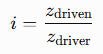
This gives the ratio magnitude for a simple gear pair.
3. How do you calculate output speed from gear ratio?
Divide input speed by the reduction ratio:
For example, an input speed of 1,200 rpm through a 3:1 reduction gives an ideal output speed of 400 rpm.
4. How does gear ratio affect torque?
A reduction ratio increases output torque in proportion to the ratio in an ideal transmission. In practice, output torque is lower than the ideal value because of transmission losses, so efficiency must be included in the calculation.
5. What is the difference between gear ratio and gear reduction ratio?
Gear ratio is a general term for the rotational relationship between connected members. Gear reduction ratio usually refers specifically to a configuration in which output speed is lower than input speed. Always check the stated convention when comparing specifications.
6. How do you calculate the overall ratio of a multi-stage gearbox?
For conventional stages with consistently defined reduction ratios, multiply the individual stage ratios. For example, a 3:1 stage followed by a 4:1 stage gives an overall reduction of 12:1.
7. How do you calculate the ratio of a worm gear set?
Divide the worm wheel’s tooth count by the number of starts on the worm. The result is the nominal ratio for the simple worm gear arrangement.
8. How do you calculate gear ratio for a planetary gearbox?
Use the tooth counts and the appropriate planetary kinematic equation. The result depends on which member is fixed, which member is the input, and which member is the output.
9. How do you determine the gear ratio of a large girth gear and pinion?
For a simple girth gear and pinion pair, divide the girth gear’s tooth count by the pinion’s tooth count. The result gives the reduction ratio between those two members, not necessarily the overall ratio from the motor.
10. What information is needed to replace an industrial gear without changing the required ratio?
Provide the existing tooth counts, mating gear information, tooth geometry, dimensions, operating speeds, transmitted torque, and duty cycle. The replacement must preserve the intended ratio and be compatible with the mating gear while meeting the project’s material, accuracy, and load-capacity requirements.
Conclusion
Gear ratio is a foundational calculation for designing, selecting, and maintaining industrial transmissions. Tooth counts provide the most direct calculation for a simple gear pair, while multi-stage and planetary systems require a clear understanding of their individual kinematic relationships.
For reliable industrial performance, engineers must evaluate gear ratio together with output torque, efficiency, gear geometry, load capacity, and operating conditions. Whether specifying a large girth gear and pinion, a paper machine drive gear, a sugar mill bull gear, or a custom gearbox, the goal is not merely to achieve the correct ratio—it is to achieve that ratio with a compatible, adequately rated, and maintainable transmission.