

Gear module is one of the fundamental parameters in metric gear design. It defines the relationship between a gear’s reference diameter and its number of teeth, providing a standard way to describe tooth size. Module affects gear dimensions, tooth geometry, compatibility between mating gears, and the initial considerations engineers make when designing or replacing a transmission component.
For heavy industrial machinery, understanding module is particularly important when specifying large spur gears, helical gears, girth gears, and gear-and-pinion sets. However, module alone does not determine whether a gear can carry a particular load or operate reliably. Engineers must also evaluate tooth geometry, material properties, heat treatment, manufacturing accuracy, lubrication, and operating conditions.
This guide explains the gear module formula, calculation methods, its relationship with other design parameters, and its practical role in mining, cement, sugar processing, rubber machinery, steel production, marine equipment, wind power, paper mills, and port cranes.
1. What Is Module in Gear?
Gear module is the reference diameter divided by the number of teeth, expressed in millimetres for metric gearing. It is represented by the symbol m.
For a standard cylindrical gear, the basic formula is:
m=d/z
where:
- m = gear module, in millimetres
- d = reference diameter, in millimetres
- z = number of teeth
For example, a gear with a reference diameter of 120 mm and 30 teeth has a module of 4 mm.
Module describes the scale of the gear teeth. For a given tooth count, increasing the module increases the reference diameter. Conversely, for a given reference diameter, increasing the module means fewer teeth fit around the gear.
Module is important for three main reasons:
- Gear sizing: It provides a fundamental dimension for calculating the reference diameter and related tooth geometry.
- Mating compatibility: Gears must have compatible tooth systems and geometry to mesh correctly.
- Engineering specification: It helps manufacturers identify, design, inspect, and reproduce gears, including large-module gears used in heavy industrial machinery.
Module is not a direct measure of gear strength. Two gears with the same module may have substantially different load capacities because of differences in face width, tooth profile, material, heat treatment, manufacturing quality, and operating loads.
2. Gear Module Formula and Calculation
The Basic Gear Module Formula
The fundamental relationships are:
m=d/z
d=mz
The first calculates module from reference diameter and tooth count. The second calculates reference diameter when module and tooth count are known.
For two standard external spur gears with compatible geometry, the nominal center distance is:
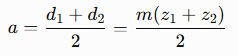
Here, a is the distance between the gear axes, while d1,d2 and z1,z2 represent the reference diameters and tooth counts of the two gears.
These basic equations apply to standard cylindrical gear geometry. Helical gears require attention to whether the specified module is normal or transverse, while bevel and worm gears require their own geometry-specific definitions and calculations.
Worked Examples of Gear Module Calculation
Example 1: Calculate module from known dimensions
Suppose a standard cylindrical gear has:
- Reference diameter: 180 mm
- Number of teeth: 45
Then:
m=180/45=4mm
The calculated module is 4 mm.
Example 2: Calculate reference diameter from module
Suppose a gear has a module of 6 mm and 50 teeth:
d=6*50=300mm
Its reference diameter is 300 mm.
These calculations are straightforward when reliable design data are available. For a physical gear without drawings, however, engineers must establish the tooth count and determine the correct reference geometry rather than simply substituting the measured outside diameter into the formula. Our walkthrough on how to calculate module of gear covers that reverse process step by step, including the centre-distance method and the cases where profile shift makes a measured result unreliable.
Module, Tooth Pitch, and Diametral Pitch
Module is closely related to circular pitch, the distance measured along the reference circle between corresponding points on adjacent teeth:
p=πm
For a module of 4 mm, the circular pitch is approximately 12.57 mm.
Metric gearing commonly specifies tooth size using module. Inch-based gearing often uses diametral pitch (DP), defined as the number of teeth per inch of reference diameter.
For compatible standard transverse definitions, the conversion relationship is:
m=25.4/DP
Module is a length-based measure, while diametral pitch is an inverse measure. Their numerical values therefore move in opposite directions: a larger module corresponds to a smaller diametral pitch.
When replacing imported or legacy gearing, confirm the actual tooth system before ordering. A metric module designation should not be treated as interchangeable with an inch-based diametral-pitch designation without checking the full tooth geometry.
3. How Gear Module Affects Gear Design
Module and Tooth Size
Module establishes the scale of the teeth, but its effect must be considered alongside the gear’s overall dimensions and design requirements.
For a fixed tooth count, a larger module produces a larger reference diameter. For a fixed reference diameter, a larger module means fewer teeth. This affects the space available for teeth, tooth proportions, gear dimensions, and the initial assessment of load capacity.
A larger module can support a robust tooth design, but it does not automatically produce a stronger or more reliable gear. Engineers must consider:
- Tooth-root bending stress and the risk of fatigue cracking.
- Contact stress and the risk of surface pitting.
- Face width and the distribution of load across the tooth.
- Material strength, heat treatment, and manufacturing quality.
- Operating speed, shock loading, lubrication, and alignment.
For large industrial drives, module selection is part of a complete gear design or rating calculation, not a stand-alone strength decision.
Module, Center Distance, and Gear Ratio
For a standard external spur gear pair with compatible geometry, center distance can be calculated using:
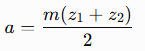
Consider two gears with a module of 5 mm, one with 20 teeth and the other with 60 teeth:
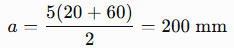
The nominal center distance is 200 mm under the stated assumptions.
The gear ratio, however, is determined by tooth counts:

For this pair, the ratio is 60/20=3, or 3:1 when the larger gear is driven by the smaller gear.
Module establishes tooth size and contributes to gear dimensions; it does not independently establish the ratio. Profile shift, modified tooth geometry, and other design features can change the center distance or require more detailed calculations.
Module Compatibility and Gear Interchangeability
Two gears cannot be assumed to mesh correctly simply because their reference diameters are similar. Their tooth systems must be compatible.
For conventional external spur gears, engineers normally verify:
- Matching module.
- Compatible pressure angle and tooth profile.
- Appropriate tooth counts and center distance.
- Compatible tooth thickness, backlash, and any profile modifications.
For helical gears, it is important to distinguish normal module from transverse module. The relationship between these depends on the helix angle. Using a normal module as though it were a transverse module can lead to incorrect dimensions and incompatible mating geometry.
Internal gears, bevel gears, and worm gearing also require their specific geometric definitions. A replacement gear must be checked against the actual mating component and transmission arrangement, not just a nominal module value.
4. Common Gear Modules and Large-Module Gears
Standard Modules and Module Selection
Metric gear design uses standardized preferred module values to promote consistency in design and manufacturing. ISO 54 specifies preferred module series for applicable cylindrical gearing; engineers should consult the relevant standard and design requirements when selecting a value.
Standardization can simplify tooling selection, manufacturing planning, and replacement work. However, not every existing gear uses a preferred module, and some custom or legacy designs may require non-standard geometry.
Module selection should account for:
- Required torque and the nature of the transmitted load.
- Tooth-root strength and contact durability.
- Gear diameter, tooth count, and available installation space.
- Face width, shaft arrangement, and alignment.
- Material, heat treatment, and manufacturing capability.
- Required service life and maintenance conditions.
A design may require a larger module to meet strength or dimensional requirements, but the final selection should be verified using appropriate gear-design calculations.
Large-Module Gears for Heavy-Duty Applications
Large-module gears are used where tooth dimensions and transmission requirements suit heavy industrial loads and large machinery. They may include large spur gears, helical gears, herringbone gears, girth gears, and matched gear-and-pinion sets.
Typical applications include mining mills, cement kilns, sugar mills, steel plant drives, and selected heavy-duty lifting systems. Some of these machines use open gearing, while others rely on enclosed gearboxes or different drive arrangements.
The term large module does not have one universal threshold that applies to every industry. It should be understood in the context of the gear’s dimensions, design, load, and manufacturing requirements.
For large-diameter gears, the module must be considered together with blank geometry, tooth cutting, heat-treatment capability, inspection access, transport, installation, and alignment. A technically suitable tooth size is only one part of a manufacturable and serviceable design.
5. Module, Gear Strength, Accuracy, and Manufacturing
Module and Load Capacity
Module influences tooth geometry and is an important input to gear strength calculations. Nevertheless, gear capacity depends on the complete design.
Tooth-root bending strength is affected by the tooth form, root geometry, material properties, face width, and applied loads. Surface durability depends on contact conditions, material and hardness, lubrication, alignment, and load distribution.
For large-module gearing, engineers should also evaluate the consequences of:
- Shock loads and repeated starts or reversals.
- Shaft and housing deflection.
- Misalignment and uneven contact across the face width.
- Contamination or inadequate lubrication.
- Operating speed and thermal conditions.
For a girth gear and pinion, for example, nominal module does not establish whether the pair can drive a loaded mill reliably. Both components, their mounting arrangements, and the actual operating loads must be considered.
Materials, Heat Treatment, and Tooth Quality
Heavy-duty gears may be manufactured from suitable grades of alloy steel or cast steel, depending on the gear dimensions, load, design, and production route. Material selection should balance strength, toughness, wear resistance, manufacturability, and the requirements of heat treatment.
Possible processes include casting or forging, machining, tooth cutting, heat treatment, and tooth finishing. Case hardening can provide a hard surface with a tougher supporting core for appropriate designs, but it is not suitable or necessary for every gear. The process must match the material, section size, required properties, and service conditions.
Gear accuracy is another independent consideration. ISO 1328-1 establishes a flank-tolerance classification system for specified cylindrical involute gears. Applicable AGMA standards may also be used for relevant gear quality and rating requirements. The correct standard depends on the gear type and engineering specification.
An accuracy grade does not by itself define load capacity or guarantee performance in an assembled transmission. Engineers must specify the relevant quality requirements and evaluate the full gear system.
Manufacturing and Inspection of Large Gears
Manufacturing a large-module gear requires control of both the blank and the finished tooth geometry. Depending on the design, production may include:
- Blank production by an appropriate casting, forging, or other process.
- Rough machining and preparation of mounting features.
- Tooth cutting using a suitable manufacturing method.
- Heat treatment and any required finishing operations.
- Dimensional inspection and verification of specified tooth characteristics.
For a large industrial gear, inspection requirements should be agreed upon before production. Relevant checks may include tooth count, module, reference diameter, pressure angle, tooth thickness, runout, tooth flank deviations, and other drawing-specific tolerances.
A manufacturer should also assess practical constraints such as equipment capacity, heat-treatment limitations, transport, installation, and access for future maintenance. These factors become particularly important for large girth gears and custom replacement components.
6. How Gear Module Is Used Across Major Industries
Mining and Cement Plant Gears
Mining equipment includes ball mills, SAG mills, rod mills, and crushers, each with different transmission requirements. Large mill drives may use a girth gear and pinion, with module forming part of the specification for the mating teeth. Load variation, shock loading, lubrication, and alignment are important when designing or replacing mining mill gears.
Cement plants use gearing in rotary kilns, cement mills, and other processing equipment. Rotary kiln girth gears and cement mill drive gears must be specified according to their actual geometry and operating loads. During girth gear replacement, engineers should verify module, tooth count, pressure angle, face width, mounting, and mating-pinion compatibility.
Sugar Mills and Rubber Machinery
Sugar mills use bull gears, crown gears, pinions, and other drive components in cane mills, crushers, and shredders. These gears must transmit the required torque while accommodating the machine’s load conditions and service environment.
Rubber machinery uses gears in open mixing mills, internal mixers such as Banbury mixers, calenders, refiners, and extruders. Depending on the machine, gearing may drive rollers, mixing rotors, or enclosed transmissions. Module must be considered alongside tooth geometry, speed, torque, and compatibility with the mating gear when specifying rubber machinery replacement gears.
Steel Plants and Heavy Industrial Drives
Steel plants use gears in rolling mills, pinion stands, coilers, recoilers, converter tilting systems, sinter plants, and material-handling equipment. Many of these applications experience high torque, reversing loads, frequent starts, or demanding operating cycles.
Module selection must be supported by calculations that account for the load spectrum, tooth-root strength, contact durability, material properties, and required service life. Large steel mill gears also require attention to manufacturing accuracy, alignment, and the condition of the associated shafts and bearings.
Marine, Port Cranes, and Lifting Equipment
Marine and shipyard machinery includes reduction gear components, dredger cutter-head drives, winch gears, ship-lift drives, and crane transmission systems. Gear design requirements vary considerably between an enclosed marine gearbox and a large exposed drive.
Port cranes use slewing ring gears and pinions, hoist gears, and luffing drives. Module is one part of the tooth geometry specification, alongside load reversals, backlash, mounting accuracy, duty cycle, and required reliability. Replacement parts must match the actual drive design rather than being selected by diameter alone.
Wind Turbines and Power Transmission
Wind turbines may use planetary gearboxes containing sun, planet, and internal ring gears. Separate yaw and pitch systems may use ring gears and pinions to position the nacelle or adjust the blades.
The module definition and geometry must match the particular gear arrangement. For replacement work, engineers should verify the original specification, load conditions, tooth geometry, and manufacturing requirements rather than assuming that gearbox planetary gears and yaw-system gears share the same design.
Paper Mills and Paper-Making Machinery
Paper machine drive systems may include gears for refiners, pulpers, dryer cylinders, Yankee dryers, calenders, and rewinders. Depending on the machine design, these gears transmit power to individual sections or help maintain the required speed relationships between connected components.
Paper mill heavy-duty gears must be suitable for continuous operation and the loads of the specific application. For dryer cylinder drive gears or other paper machine replacement gears, module should be verified together with tooth geometry, face width, material, mounting interfaces, and mating-gear compatibility.
7. Quick-Reference Table: Gear Module and Industrial Applications
| Gear type or application | Module-related considerations | Common material or treatment options | Key specification checks |
|---|---|---|---|
| Mining mill girth gears | Tooth size, gear diameter, mating-pinion geometry | Suitable cast or forged steels; treatment depends on design | Tooth geometry, alignment, contact pattern, lubrication |
| Cement kiln and mill gears | Large gear dimensions and load requirements | Cast or forged steel options according to design | Tooth count, module, mounting, load distribution |
| Sugar mill bull gears | High torque and application-specific tooth geometry | Suitable cast or forged materials | Tooth condition, mating pinion, operating loads |
| Rubber machinery gears | Speed, torque, and transmission arrangement | Suitable steels and application-specific heat treatment | Tooth compatibility, backlash, duty cycle |
| Steel mill drive gears | Reversing loads, shock loads, and tooth strength | Suitable alloy steels or other specified materials | Geometry, accuracy, alignment, fatigue resistance |
| Crane slewing gears and pinions | Gear arrangement, positioning requirements, and load reversals | Suitable steels with protection appropriate to the environment | Module, pressure angle, mounting, backlash |
| Wind turbine gears | Gear-specific module definition and load distribution | Application-specific alloy steels and heat treatments | Planetary geometry or yaw/pitch drive compatibility |
| Paper machine drive gears | Continuous duty and required speed relationship | Suitable materials according to load and design | Tooth geometry, alignment, lubrication, replacement fit |
Material and treatment choices are indicative, not universal prescriptions. Final selection requires a design-specific engineering assessment.
8. How to Identify or Specify the Correct Module for a Gear
Calculate Module from Drawings or an Existing Gear
If a reliable drawing provides the reference diameter and tooth count, module can be calculated using m=d/z. When inspecting a physical gear, identifying module may be more difficult because the reference diameter is not directly measurable like the outside diameter.
For a standard external spur gear without profile shift, the outside diameter can sometimes help estimate module using the appropriate tooth-geometry relationship. However, this shortcut should not be applied blindly to modified gears, helical gears, internal gears, or other configurations.
A proper identification process should verify:
- Tooth count and gear type.
- Module definition and pressure angle.
- Reference diameter and tooth thickness.
- Helix angle and normal/transverse module, where applicable.
- Profile modifications, backlash, and mating-gear geometry.
If the original drawing is unavailable, measurement and engineering verification are preferable to relying on one dimension.
Specify Module for Custom and Replacement Gears
When requesting a custom industrial gear, provide the following information wherever available:
- Gear type, module, tooth count, and pressure angle.
- Reference diameter, face width, and other relevant dimensions.
- Helix angle or other geometry-specific parameters.
- Material, heat treatment, and accuracy requirements.
- Mounting interfaces, shaft details, and center distance.
- Input power, speed, torque, duty cycle, and operating environment.
For large-module gears, also discuss manufacturing capability, inspection methods, transport, installation, and maintenance requirements.
A qualified gear manufacturer should verify the complete tooth geometry and its compatibility with the mating component. This is particularly important for large-diameter gears, girth gears, and replacement gear-and-pinion sets, where dimensional errors can cause costly installation or operating problems.
9. Frequently Asked Questions About Gear Module
1. What is module in a gear?
Module is the ratio of a gear’s reference diameter to its number of teeth, expressed in millimetres for metric gearing. It is a fundamental measure of tooth size and a key parameter in gear geometry.
2. How do you calculate gear module?
Divide the reference diameter by the number of teeth:
m=d/z
Use the correct reference diameter rather than the outside diameter.
3. What is the difference between module and pitch diameter?
Module describes tooth size relative to tooth count, while reference or pitch diameter describes the gear’s reference size. For a standard cylindrical gear, the reference diameter equals module multiplied by the number of teeth.
4. What is the relationship between module and circular pitch?
For standard metric cylindrical gearing, circular pitch is calculated as p=πm. It represents the distance along the reference circle between corresponding points on adjacent teeth.
5. What is the difference between module and diametral pitch?
Module is expressed in millimetres per tooth, while diametral pitch is the number of teeth per inch of reference diameter. They are inverse measures of tooth size and require a proper conversion when comparing metric and inch-based gearing.
6. Does a larger gear module mean a stronger gear?
Not necessarily. A larger module generally produces larger teeth, but load capacity also depends on tooth geometry, face width, material, heat treatment, manufacturing accuracy, lubrication, and operating loads.
7. Do two mating gears need to have the same module?
Conventional external spur gears generally need compatible modules, pressure angles, and tooth geometry. Helical and other gear types require additional checks because module definitions and meshing relationships can differ.
8. How do you find the module of an existing gear?
Start with verified design information, or determine the tooth count and establish the correct reference geometry through measurement. Outside diameter alone is insufficient for reliable identification unless an appropriate gear-specific relationship and its assumptions are confirmed.
9. What module is suitable for a large industrial gear or girth gear?
There is no universal module suitable for every large gear. Selection depends on torque, tooth strength, diameter, tooth count, face width, material, operating conditions, manufacturing capability, and the mating gear’s geometry.
10. What information is needed to manufacture a custom replacement gear?
Provide the gear type, module definition, tooth count, pressure angle, reference diameter, face width, material, heat treatment, accuracy requirements, mounting dimensions, and operating loads. Drawings and information about the mating gear help the manufacturer verify compatibility.
Gear module is a foundational parameter in metric gear design, but it should never be treated as a complete specification by itself. Reliable gear selection requires compatible tooth geometry, adequate load capacity, appropriate materials and manufacturing processes, and consideration of the operating environment.
For large industrial gears used in mining, cement, sugar processing, rubber machinery, steel plants, marine equipment, wind turbines, paper mills, and port cranes, verifying module alongside the complete gear specification is essential for dependable performance and successful replacement.