

Helical gears are widely used in industrial power transmission because their angled teeth engage progressively, providing smooth motion transfer and generally quieter operation than comparable spur gears. They are found in enclosed gearboxes, high-speed drives, heavy-duty reducers, and machinery that requires reliable transmission of power under continuous or fluctuating loads.
However, selecting a helical gear involves more than choosing a tooth count or reduction ratio. Engineers must consider module, helix angle, tooth geometry, axial thrust, material properties, lubrication, manufacturing accuracy, and the operating conditions of the complete drive system.
This guide explains how helical gears work, compares their main types, examines key design parameters, and explores their applications in paper mills, rubber machinery, mining, cement production, sugar processing, steel plants, marine systems, wind turbines, and port cranes.
1. What Is a Helical Gear?
A helical gear is a cylindrical gear whose teeth follow a helix around the gear body rather than running parallel to its axis, as they do on a spur gear. This angled tooth arrangement allows contact to develop progressively across the tooth face, which can improve smoothness and reduce operating noise under suitable conditions.
Helical gears are commonly used between parallel shafts. Internal helical gears can also mesh with external helical gears, while crossed-helical arrangements can transmit motion between certain non-parallel, non-intersecting shafts.
Several geometric terms are essential to helical gear design:
- Module: A metric measure of tooth size. For helical gears, engineers must specify whether the normal module or transverse module is being used.
- Reference diameter (pitch diameter): The diameter used to define the gear’s reference geometry and meshing relationship.
- Helix angle: The angle between the tooth direction and the gear axis, defined at the reference cylinder.
- Normal pressure angle: The pressure angle measured in the plane normal to the tooth helix.
- Face width: The axial width of the toothed portion of the gear.
- Backlash: The clearance between mating tooth flanks when the gears are assembled.
For a standard cylindrical helical gear, the normal and transverse modules are related by the helix angle:
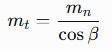
where mt is the transverse module,mn is the normal module, and β is the helix angle. The reference diameter is then related to tooth count by d=mt*z.
These relationships matter when specifying, manufacturing, or replacing a gear. Two gears with the same tooth count and nominal diameter may not be compatible if their module convention, helix angle, pressure angle, or tooth geometry differs.
2. How Do Helical Gears Work?
When two helical gears mesh, the angled teeth come into contact progressively rather than engaging across the entire tooth face simultaneously. This gradual engagement can reduce sudden changes in transmitted force and help produce smoother operation.
For a compatible external helical gear pair on parallel shafts, the gear ratio is determined by the tooth counts, just as it is for a spur gear pair:
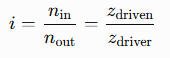
where n represents rotational speed and z represents tooth count. A larger driven gear produces a speed reduction and, subject to transmission losses, a corresponding increase in output torque.
Helical gearing also generates forces that engineers must account for:
- Tangential force: Transmits torque at the reference diameter.
- Radial force: Acts between the mating gears and contributes to shaft and bearing loading.
- Axial force: Arises from the helix angle and acts along the gear axis.
The axial force is a major difference between single helical and spur gearing. Bearings, shafts, and housings must be designed to withstand the resulting loads without excessive deflection or misalignment.
In real applications, efficiency and operating temperature depend on the gear geometry, surface condition, lubrication, speed, load, bearing losses, and gearbox design. Helical gears are therefore not automatically more efficient than every alternative; their suitability must be assessed under the actual operating conditions.
3. Main Types of Helical Gears
3.1 Single Helical Gears
Single helical gears have teeth inclined in one direction across the gear face. They offer progressive engagement and are widely used in parallel-shaft gearboxes, industrial reducers, and machine drives.
Their main design consideration is axial thrust. The bearing arrangement must support the thrust force while maintaining shaft position and suitable tooth contact. Engineers should also check shaft stiffness, housing rigidity, lubrication, and the effects of thermal expansion.
3.2 Double Helical and Herringbone Gears
Double helical gears use two tooth sections with opposite helix directions. Herringbone gears have opposing helical tooth patterns that form a continuous V-shaped arrangement.
Because the two helix directions generate opposing axial forces, a properly designed arrangement can substantially balance axial thrust. This makes double helical and herringbone gearing useful in selected high-torque industrial transmissions where smooth operation and load capacity are important.
They may be found in heavy-duty machinery and large transmission systems. However, manufacturing complexity, tooth geometry, alignment, and inspection requirements must be considered. The terms are related but should not be treated as identical in every construction.
3.3 Helical Gear Pairs and Multi-Stage Gearboxes
A helical gear pair can provide a moderate speed change in a single stage. Where a larger reduction ratio is required, multiple gear pairs can be arranged in a multi-stage gearbox.
Compound arrangements allow gears on a common shaft to connect successive stages. The overall ratio is the product of the individual stage ratios, while overall efficiency reflects losses across the entire transmission.
Multi-stage helical gearboxes are used in industrial drives that require high output torque, controlled speed, and a compact enclosed transmission. Design must account for cumulative losses, bearing loads, heat generation, lubrication distribution, and the physical space available for the gears and shafts.
3.4 Helical Gears Compared with Spur and Bevel Gears
Helical, spur, and bevel gears serve different transmission requirements.
- Helical gears: Angled teeth, progressive engagement, and axial thrust; commonly used for parallel-shaft enclosed drives.
- Spur gears: Straight teeth parallel to the axis, with no theoretical axial thrust from the gear mesh; often simpler to manufacture and analyze.
- Bevel gears: Conical tooth geometry for transmitting motion between intersecting shafts, with tooth geometry depending on the bevel gear design.
The choice should reflect shaft layout, load, speed, noise requirements, bearing capacity, cost, and maintenance conditions. Helical gearing is not a direct substitute for bevel gearing when the transmission requires a change in shaft direction.
4. Key Helical Gear Design Parameters
4.1 Module, Pitch Diameter, and Tooth Geometry
Helical gear geometry must be specified consistently so the gear meshes correctly with its mating component. Important parameters include:
- Normal and transverse module: The normal module is measured in the plane normal to the tooth helix, while the transverse module is measured in the plane of gear rotation. The distinction is essential when calculating dimensions and specifying replacement gears.
- Helix angle and hand: Parallel-axis external helical gears generally require equal helix-angle magnitudes and opposite hands. Handedness affects both compatibility and the direction of axial thrust.
- Pressure angle and tooth profile: These influence tooth strength, contact conditions, and compatibility between mating gears.
- Face width and backlash: Face width affects load distribution and capacity, while backlash must accommodate the intended operating conditions, manufacturing tolerances, lubrication, and thermal effects.
- Center distance and alignment: Incorrect center distance, shaft deflection, or misalignment can cause uneven tooth contact and premature wear.
The design must also account for tooth modifications, such as profile relief or lead crowning, where required to accommodate elastic deformation and improve load distribution. These modifications should be based on the expected operating conditions rather than applied indiscriminately.
4.2 Load Capacity, Speed, and Efficiency
A helical gear set must be rated for the actual torque, speed, duty cycle, and expected service life. A design that meets nominal power requirements may still fail if it experiences frequent starts, reversals, shock loads, or significant misalignment.
Engineers should evaluate:
- Tooth-root bending strength and flank contact fatigue.
- Scuffing risk, sliding conditions, and lubrication performance.
- Dynamic loads, vibration, and noise at the operating speed.
- Shaft and bearing loads, including axial thrust.
- Heat generation, oil supply, and thermal stability.
For cylindrical involute helical gears, the ISO 6336 series provides methods for calculating load capacity within its stated scope. The chosen method and assumptions must suit the gear geometry and application; a rating calculation alone does not guarantee the performance of the assembled transmission.
4.3 Materials, Heat Treatment, and Gear Accuracy
Through-hardened steels may suit applications requiring a balance of strength, toughness, and manufacturing practicality. For heavily loaded gears, case-hardened alloy steels can provide a wear-resistant surface with a tougher supporting core. Carburizing and hardening are common options, but material and treatment selection must reflect gear size, loading, fatigue requirements, and manufacturing capability.
Accuracy is equally important. Tooth profile, helix deviation, pitch-related deviations, runout, and surface finish affect contact distribution, vibration, and operating life. ISO 1328-1 provides a classification framework for deviations relevant to cylindrical gear tooth flanks. The required accuracy class should be chosen for the application rather than assumed from a generic description such as “high precision.”
5. Industrial Applications of Helical Gears
5.1 Paper Mills and Paper Machine Drive Systems
Helical gears are used in suitable enclosed drives for paper machines, refiners, pulpers, calenders, rewinders, and selected dryer-section or Yankee dryer systems. Their progressive engagement can support smooth power transmission in machinery that operates continuously.
Paper mill drive gears must be assessed for load variation, alignment, lubrication, and the operating requirements of the driven equipment. Not every dryer cylinder or paper machine drive uses helical gears; the correct configuration depends on the original transmission design.
5.2 Rubber Machinery
Rubber machinery uses helical gears in selected drive systems for rubber mills, internal mixers, Banbury mixers, calenders, and extruders. These applications can involve high torque and fluctuating process loads, making tooth strength, shaft stiffness, and lubrication important design considerations.
When replacing rubber mill gears or internal mixer drive gears, engineers should inspect mating components and supporting bearings as well as the damaged gear. Replacing one component without correcting overload, misalignment, or lubrication problems may lead to another failure.
5.3 Mining Equipment
Helical gears are used in enclosed reducers and selected transmission stages for crushers, conveyors, ball mills, SAG mills, and rod mills. They can provide speed reduction and torque transmission where the gearbox configuration suits the required load and shaft arrangement.
Large mining mills may instead use an open girth gear and pinion drive. A ball mill girth gear, SAG mill girth gear, or mining mill open gear should not automatically be classified as a helical gear. Engineers must identify the actual tooth geometry before selecting a replacement or specifying manufacturing requirements.
5.4 Cement Plants and Rotary Kilns
Cement plants use helical gearing in suitable enclosed drives for cement mills, vertical mills, roller presses, and auxiliary equipment. The transmission must accommodate continuous duty, operating torque, lubrication requirements, and thermal conditions.
Rotary kilns commonly use a large girth gear and pinion arrangement rather than a conventional enclosed helical gearbox at the main drive interface. For kiln gear replacement, alignment, tooth contact, mounting, and operating history are critical to reliable performance.
5.5 Sugar Mills
Sugar mill gearboxes may use helical gears in reduction stages for cane preparation, shredding, and milling equipment. Their suitability depends on the drive architecture and the required torque and speed relationship.
Large sugar mill bull gears, crown gears, and open gears are distinct components whose geometry must be confirmed individually. When ordering a cane mill replacement gear or sugar mill reduction gear, use drawings or verified measurements to establish compatibility.
5.6 Steel Plants and Rolling Mills
Helical gears are used in suitable enclosed drives for rolling mills, coilers, recoilers, and material-handling machinery. Steel production may impose reversing loads, frequent acceleration, and high torque peaks.
Design and maintenance should address fatigue resistance, backlash, alignment, bearing capacity, and lubricant condition. For large steel mill gears or replacement gears, the complete operating load history is important when assessing whether the original design remains suitable.
5.7 Marine and Shipboard Transmission Systems
Helical gears can form part of marine reduction gearboxes and auxiliary transmission systems where the shaft arrangement and operating requirements are compatible. Depending on the application, the complete gearbox may also incorporate bevel or planetary stages.
Marine gear design must consider load transmission, vibration, lubrication reliability, corrosion protection, and maintenance access. Large marine drive gears and ship main reduction gears should be specified according to their actual gearbox architecture, not by application name alone.
5.8 Power Generation and Wind Turbines
Power transmission systems may use helical gearing where speed conversion, shaft arrangement, and operating loads make it appropriate. Wind turbine gearboxes can combine planetary stages with parallel-axis helical stages, depending on the design.
Wind turbine yaw and pitch systems commonly use ring gears and pinions as separate mechanisms. These should not be confused with helical gearbox gears: tooth geometry, mounting arrangements, and operating functions may differ substantially.
5.9 Port Cranes and Heavy Material Handling
Helical gears are used in suitable enclosed reducers for crane hoisting, trolley travel, and luffing drives. Their application depends on the transmission layout, required torque, operating cycle, and available space.
Port crane and container crane systems must withstand cyclic loads, acceleration, braking events, and potentially severe duty. Slewing mechanisms may use a separate slewing ring gear and pinion, so the actual component design should be confirmed before specifying replacement parts.
6. Common Helical Gear Failure Modes and Prevention
Helical gear failures can originate in the teeth, bearings, lubrication system, shafts, housing, or installation. The following table links common symptoms to likely causes and practical inspection actions.
| Failure mode | Likely causes | Inspection or corrective action |
|---|---|---|
| Tooth-root cracking or breakage | Bending overload, shock loads, material defects, or stress concentrations | Review load history, tooth rating, material quality, and fracture surfaces |
| Pitting or surface fatigue | Repeated contact stress, inadequate load capacity, or unsuitable lubrication | Inspect tooth flanks, confirm the rating basis, and review lubricant condition |
| Scuffing or scoring | Lubrication film breakdown, high sliding severity, or excessive temperature | Check oil supply, viscosity, temperature, loading, and surface condition |
| Uneven tooth wear | Misalignment, shaft deflection, incorrect contact pattern, or contamination | Inspect bearings, alignment, tooth contact, lubricant cleanliness, and housing stiffness |
| Excessive noise or vibration | Tooth deviations, damaged teeth, backlash issues, or bearing problems | Check tooth geometry, runout, backlash, bearings, and vibration trends |
| Axial bearing damage | Excessive or incorrectly supported thrust, or shaft-location problems | Verify helix direction, axial forces, bearing arrangement, and shaft positioning |
A failure investigation should establish the root cause before replacement. Gear damage may be a symptom of broader problems, including poor alignment, insufficient lubrication, foundation movement, or unexpected operating loads.
7. How to Select the Right Helical Gear or Gearbox
A practical selection process begins with the required input power, input and output speeds, reduction ratio, output torque, and direction of rotation. Engineers should then establish the operating duty, expected service life, shock loads, installation space, shaft arrangement, and maintenance constraints.
Before choosing a gear set, confirm:
- Required tooth geometry, module convention, helix angle, pressure angle, and center distance.
- Bending and contact-fatigue capacity under the actual load spectrum.
- Material, heat treatment, accuracy, lubrication, and thermal requirements.
- Bearing capacity, shaft stiffness, housing rigidity, and axial-thrust support.
- Inspection access, replacement availability, and supplier manufacturing capability.
A standard gearbox may be appropriate where its ratings and interfaces meet the application requirements. Custom helical gears may be necessary when existing machinery has special geometry, unusual dimensions, or replacement requirements that standard components cannot satisfy.
For large industrial gears, supplier evaluation should include manufacturing capacity, tooth-cutting and finishing capabilities, heat-treatment control, dimensional inspection, and experience with the required gear type. A supplier’s maximum gear diameter alone does not establish that it can meet the required accuracy or load rating.
8. Helical Gear Manufacturing, Inspection, and Replacement
8.1 Manufacturing and Quality Control
Helical gear manufacturing can include blank machining, tooth cutting or generating, heat treatment, and finishing operations such as grinding where specified. The process depends on material, size, tooth geometry, accuracy requirements, and the intended production route.
Inspection may include tooth count, reference dimensions, profile and helix deviations, runout, hardness, surface condition, and other drawing-defined characteristics. The relevant ISO or AGMA requirements should be selected according to the gear type and the specific rating or inspection task.
For heavy-duty or high-speed gearing, quality control should also consider mating-gear compatibility and the effects of assembly alignment. Accurate individual gears cannot compensate for an incorrectly assembled or inadequately supported transmission.
8.2 Custom Helical Gear Replacement
When requesting a custom helical gear or replacement industrial gear, provide as much verified information as possible:
- Tooth count, normal or transverse module, pressure angle, helix angle, and helix hand.
- Reference diameter, face width, bore, keyway, splines, and mounting interfaces.
- Material, heat treatment, hardness, and required accuracy.
- Mating gear information, center distance, operating speed, torque, and duty cycle.
- Drawings, inspection records, lubrication conditions, and failure history, where available.
Matching the outside diameter alone is insufficient. The replacement must mesh correctly with its mating gear and suit the shaft interfaces, operating loads, and supporting structure. If the original gear failed, the cause should be investigated before finalizing the replacement design. For a helical gear replacement in a high-speed drive, confirming the helix angle, hand, and normal module up front avoids costly fit-up and noise problems after installation.
9. Frequently Asked Questions About Helical Gears
9.1 What is a helical gear and how does it work?
A helical gear is a cylindrical gear with teeth inclined at a helix angle to its axis. The teeth engage progressively, transmitting rotational motion and torque between compatible gears.
9.2 What is the difference between helical and spur gears?
Spur gears have teeth parallel to the gear axis, while helical gears have angled teeth. Helical gears generally provide smoother engagement but generate axial thrust that must be considered in shaft and bearing design.
9.3 What are the advantages and disadvantages of helical gears?
Advantages include progressive engagement and potentially lower noise and vibration under suitable conditions. Disadvantages include axial thrust in single-helical arrangements, sliding contact, and potentially greater design or manufacturing complexity.
9.4 What is the helix angle of a gear?
The helix angle is the angle between the tooth direction and the gear axis, measured at the reference cylinder. It affects tooth geometry, contact characteristics, and the axial force generated during operation.
9.5 How do you calculate a helical gear ratio?
For a compatible external gear pair, the reduction ratio is the driven gear’s tooth count divided by the driving gear’s tooth count. The helix angle affects geometry and force relationships but does not independently determine the gear ratio.
9.6 Why do helical gears generate axial thrust?
The angled tooth orientation causes the transmitted mesh force to have an axial component. The resulting thrust must be accommodated by the bearings, shaft location, and housing; opposing helix directions can balance thrust in a properly designed double-helical arrangement.
9.7 Are helical gears suitable for heavy-duty industrial applications?
Yes, where the gear geometry, tooth rating, materials, lubrication, bearings, and supporting structure are designed for the actual loads. Suitability must be verified for the specific duty cycle and operating environment.
9.8 Which materials are used for heavy-duty helical gears?
Through-hardened steels and case-hardened alloy steels are common options. Selection depends on tooth size, load, fatigue life, wear requirements, manufacturing method, and the required combination of surface hardness and core toughness.
9.9 How do you identify a worn or damaged helical gear?
Warning signs include pitting, scoring, cracked teeth, abnormal wear patterns, increased noise, vibration, or changes in operating temperature. Inspection should also examine lubricant condition, alignment, bearings, and the mating gear.
9.10 What information is needed to order a custom helical gear?
Provide the tooth count, module convention, helix angle and hand, pressure angle, reference dimensions, face width, shaft interface, material, heat treatment, and operating conditions. Drawings and details of the mating gear help establish compatibility and avoid costly replacement errors.
Helical gears are valuable components in high-speed and heavy-duty transmission systems, but dependable performance requires a coordinated approach to geometry, load rating, material selection, lubrication, manufacturing accuracy, and installation. For industrial applications, the right design is not simply the gear that fits; it is the gear that transmits the required power reliably throughout the intended service life.